


4
Eastwood Technical Assistance: 800.343.9353 >> [email protected]
SET-UP
• The Eastwood Manual Ironworker requires up to several hundred
pounds of handle force to operate and must be securely mounted
on a heavy, solid workbench, stand, floor etc., capable of holding
the static weight of the unit plus the ability to counter the high force
stresses from operation.
• Place the Manual Ironworker over the chosen location then mark
mounting hole locations by tracing holes in the feet.
• The use of 1/2” x 4” [m13 x 100mm] through bolts & nuts or longer
lag screws with substantial washers and attachment to a structural
member is absolutely necessary.
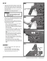
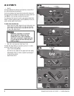
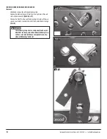
• The Eastwood Manual Ironworker is shipped with the Actuating
Arm in the downward position
(FIG 1)
requiring some partial disas-
sembly and reassembly as follows:
- Using a ¼” Drift or Punch, drive out the partially inserted Roll
Pins and set aside for reinstallation
(FIG 2)
.
- Remove the Pivot Pin
(FIG 3)
then pull the Actuating Arm stub
all the way up and over center to relieve tension of the Handle
Return Springs
(FIG 4)
.
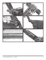
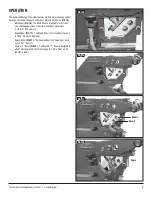
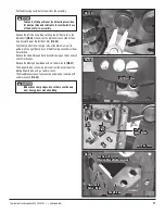
- Pull off the two Handle Return Springs
(FIG 5)
and set aside for
reinstallation noting which one is Left and which is Right.
- Keep the Actuating Arm in the upward, over-center position
(FIG 6)
.
- Replace the Handle Return Springs making sure the hooked
fingers are positioned properly just ahead of the Drive Posts
with the open loops facing rearward
(FIG 6)
.
- Replace the Roll Pins allowing them to contact the straight
fingers of the Handle Return Springs into a slight tension in the
nearest locating holes
(FIG 6
).
- Drive the Roll Pins into place with a Hammer
(FIG 7)
.
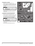
- Replace the Pivot Pin (Fig 8) then allow the Actuating Arm stub
to move forward. At this point it should be under spring tension
(FIG 8)
.
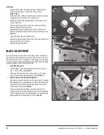
ASSEMBLY
• Assemble the two Handle sections and bolt together with the
M8 x 20mm Bolt
(FIG 9)
.
• Install assembled Handle to the Actuating Arm with the
M12 x 50mm Bolt, Washer, Lock washer and Nut
(FIG 10)
.
• The Eastwood Manual Iron Worker is ready for use.
Check for the presence of electrical, air or other
utility lines under the mounting surface before
drilling mounting holes.
FIG. 1
✓
Actuating
Arm
FIG. 2
FIG. 3
FIG. 4
Rotate up


