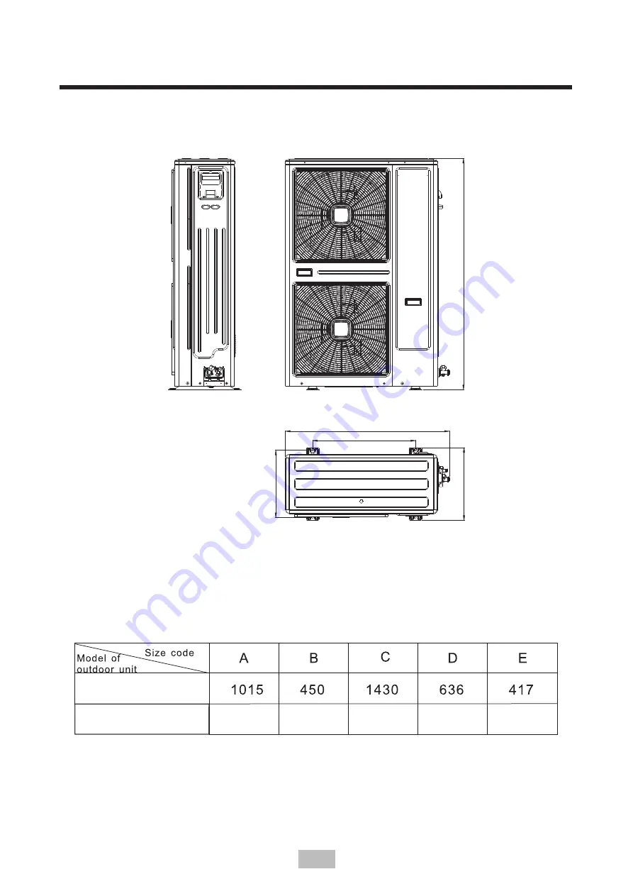
A
C
D
E
B
Figure3-2(125~224 )
Table
3
-
2
:
unit
mm
200/224
125
/
140
160
180
3.Installation of outdoor unit
4
975
400
1335
586
370
V.2
Страница 1: ...IT MANUAL DE INSTRUCCIONES INSTRUCTION MANUAL GUIDE D UTILISATION MANUAL D INSTRUÇÕES Escanee para ver este manual en otros idiomas y actualizaciones Scan for manual in other languages and further updates Manuel dans d autres langues et mis à jour Manual em outras línguas e actualizações V 2 ...
Страница 2: ...ción de la instalación 3 Instalación de la unidad exterior 4 Instalación de la tubería de conexión 5 Cableado eléctrico 6 Prueba de funcionamiento 7 Garantía 8 Disposición de eliminación 14 6 3 2 1 VWH HTXLSR FRQWLHQH JDVHV IOXRUDGRV GH HIHFWR LQYHUQDGHUR 5 FRQ 3 V 2 ...
Страница 3: ...os siempre que se les haya supervisado o instruido sobre el uso del aparato de forma segura y que comprendan los peligros que conlleva Los niños no deben jugar con el aparato La limpieza y el mantenimiento del equipo no serán realizados por niños sin supervisión Fusible de la placa principal Consulte el parámetro 5 1 en la página 15 Atención Asegúrese de que el punto de drenaje del agua sea adecua...
Страница 4: ...ebe inyectar nitrógeno a 40kgf cm2 4 0MPa del lado de gas y líquido a la vez para realizar una prueba de estanqueidad durante 24 horas 2 4 Vaciado Después de comprobar la estanqueidad de la máquina se debe vaciar 0 1MPa del lado de gas y líquido a la vez 2 5 Recarga del refrigerante 1 El volumen de refrigerante a recargar se calcula en función del diámetro y la longitud longitud real de las tuberí...
Страница 5: ...ción de ubicación de instalación 1 Debe haber espacio suficiente para la instalación y mantenimiento 2 No debe haber obstáculos a la entrada y salida de aire y no debe haber viento fuerte 3 Debe ser un lugar seco y ventilado 4 La superficie plana de apoyo debe poder soportar el peso de la unidad exterior que debe estar instalada horizontalmente sin emitir ruidos ni vibración 5 Los vecinos no deben...
Страница 6: ...ger la máquina 2 La unidad exterior se debe transportar y alzar en vertical con una inclinación de menos de 15 grados 3 Se debe prestar mucha atención durante el transporte y levantamiento de la máquina 4 Nunca sostenga la máquina por la entrada de aspiración de la carcasa o podría deformarse 3 5 Espacio de instalación y mantenimiento de la unidad exterior 1 Proporcione una base firme y adecuada p...
Страница 7: ...lica del lado por donde quiera realizar la conexión de la tubería de salida puede hacerlo en el frontal o en el lateral Figura 3 7 3 Instalación de la unidad exterior Conexión de la alimentación Salida de línea de comunicación Retire la placa de metal y puede usarse como tubería de salida 5 V 2 ...
Страница 8: ...o como se muestra en la Figura 3 9 Instale el tubo de salida curvado y el tapón junto con el chasis y luego conecte el drenaje centralizado Chasis Figura 3 9 Conexión roscada Tubo de conexión del lado del líquido 3 Instalación de la unidad exterior Tubo de desagüe curvado o tapón Tubo de desagüe curvado o tapón Tubo de desagüe curvado o tapón 6 V 2 ...
Страница 9: ...imo Φ6 4 1 4 8 7 8 3 Φ9 5 3 8 12 4 12 0 Φ12 7 1 2 15 8 15 4 Φ15 9 5 8 19 0 18 6 Φ19 1 3 4 23 3 22 9 4 1 2 Tuerca de fijación Coloque el tubo de conexión apriételo con la mano y luego use una llave para apretarlo más 4 2 Fijar la dimensión de la tubería de refrigerante y unir los tramos de la tubería Nombre de la tubería Tubería principal Tubería principal de la unidad interior Tubería de salida de...
Страница 10: ...idores específicos de la marca para todas las ramificaciones del sistema De lo contrario puede causar graves fallos en el sistema 2 Deben instalarse las unidades interiores de forma equitativa a ambos lados de los distribuidores en forma de U Modo de conexión 1 Modo de conexión 2 8 V 2 ...
Страница 11: ...9 52 Φ19 05 EVRI BP1 Φ9 52 Φ22 2 EVRI BP2 Φ12 7 Φ28 6 EVRI BP3 4 5 Diferencia de longitud y altura permitida de la tubería del refrigerante Conexión del modo 1 9 Longitud equivalente al distribuidor más cercano Distribuidor Unidades interiores La diferencia de altura entre las unidades interiores y exteriores La diferencia de altura entre las unidades interiores 4 Instalación de la tubería de cone...
Страница 12: ...ura entre las unidades interiores y exteriores Longitud real Longitud equivalente Longitud equivalente al distribuidor mas cercano Diferencia de altura entre las unidades interiores y exteriores Ud exterior arriba Ud exterior abajo La diferencia de altura entre las unidades interiores Valor permitido Longitud total de las tuberías La longitud de tubería más lejana L 100m 60m 70m Partes de la tuber...
Страница 13: ...rno del aceite Nota Cuando la altura vertical es superior a 10 metros es necesario añadir una curva de retorno de aceite en el medio Dividir los segmentos verticales en secciones no mayores de 8 metros Como se muestra en la imagen Tubo de líquido de alta presión 8m Tubo de gas de baja presión Curva de retorno del aceite 16m Conectado al primer grupo de unidades interiores Conectado al segundo grup...
Страница 14: ...interior Unidad interior Unidad interior Unidad interior Ajuste de la curva horizontal de retorno del aceite 4 8 Eliminar los materiales extraños en la tubería 1 Las tuberías de refrigerante pueden contener materiales extraños en el momento de la instalación por lo que deben ser limpiadas con nitrógeno a alta presión 2 Durante la limpieza nunca conecte la unidad interior 3 Nunca utilice refrigeran...
Страница 15: ...2 3 8 0 054 Φ12 7 1 2 0 110 4 11 Volumen de recarga de refrigerante El volumen de refrigerante que debe rellenarse R410A se calcula según el diámetro y la longitud de la tubería en el lado del líquido de las unidades exteriores e interiores Aviso El refrigerante R410A debe ser pesado para su recarga por una báscula electrónica en modo líquido Conectar la bomba de vacío Poner en marcha la bomba de ...
Страница 16: ...da de servicio se debe utilizar la herramienta especial R410A Llene el refrigerante a través de la entrada de servicio a la válvula del lado de gas y realice el bombeo de vacío simultáneamente en las válvulas del lado de líquido y de gas 4 13 Tratamiento de aislamiento de tuberías 1 Aplicar un tratamiento de aislamiento en las tuberías del lado de los gases y del lado de los líquidos respectivamen...
Страница 17: ...an diseñado por separado 2 La fuente de alimentación debe estar diseñada con un circuito de derivación independiente equipada con un protector de fuga de corriente y un interruptor manual 3 Las unidades interiores pertenecientes a un mismo sistema deben estar conectadas al mismo circuito de alimentación y encenderse y apagarse al mismo tiempo al desconectar o conectar todo el circuito Cada unidad ...
Страница 18: ...Controlador central de la unidad interior opcional Use cable apantallado y conecte la pantalla a tierra Unidad interior Unidad interior Unidad interior Fuse Fuse 5 Cableado eléctrico Fusible Interruptor Caja de distribución Caja de distribución Nota 1 Cuando la línea de señal emplea un cable apantallado de 2 núcleos la red de blindaje debe conectarse a la E del terminal cuando es un cable apantall...
Страница 19: ...s unidades interiores y exteriores Cuando sea necesario el usuario puede adquirir un controlador opcional de cable como se muestra en el cuadro de puntos Distribution box Nota Cuando la línea de energía es paralela a la línea de señal por favor ponga el cable de electricidad en sus respectivas tuberías de conexión y se debe dejar un espacio de línea adecuado 10A o menos 300mm 50A o menos 500mm 17 ...
Страница 20: ...t cooling inlet pipe temp Condenser outlet temp Outdoor ambient temp EXV Exhaust temp TS CN18 T3 T4 CN15 TP DISP CN3 CN28 CN40 5 EXV C DOWN DC MOTOR 5 Transformador 5 UP DC MOTOR RD BL BK 4 CN3 CN5 Display ext CN6 DISP1 P E Q X E Y SW1 SW2 A la ud interior L1 L2 L3 N YE Inductor R0303 Refrigerant radiator 5 4 Figura de cableado Nota la línea de alimentación donde se encuentra el transformador de c...
Страница 21: ...5 UP DCMOTOR 5 CN5 CN14 HP CN7 LP HEAT INV CN27 HEATY CN20 4WAY 4WAY CN21 SV2 SV2 CN7 N L3 L2 L1 RD BL CN22 TS CN18 TH2 Condenser middle temp Refrigerant cooling inlet pipe temp Inductor RD OG RD OG YE GN YE GN RD BL WH YE U V W DOWN DCMOTOR CN5 A la ud interior Display exterio LP HP E Y X CN6 YE GN CN3 Nota la línea de alimentación donde se encuentra el transformador de corriente atraviesa el tra...
Страница 22: ...ores y exteriores P2 Protección de baja presión E4 Fallo en el sensor de temperatura ambiente T4 P3 Protección contra la sobretensión E6 Fallo del sensor de temperatura del condensado T3 P4 Protección contra la temperatura excesiva E8 Fallo del sensor de temperatura TP P5 T3 or T3B protección de temperatura del condensador E9 Protección contra sobretensión y subtensión de CA P6 Protección de los m...
Страница 23: ...ón entre las unidades interiores y exteriores se encuentran en el mismo sistema de refrigeración o puede producirse algún fallo de funcionamiento 2 El voltaje de la fuente de alimentación está dentro de 10 del voltaje nominal 3 Compruebe y asegúrese de que la línea de alimentación y la línea de control están correctamente conectadas 4 Asegúrese de que no haya un cortocircuito antes de que el siste...
Страница 24: ...elevada acumulación de refrigerante Fig 6 3 Unidad interior 6 Prueba de funcionamiento 5 Medidas contra la sobrecarga de la concentración crítica a Para controlar la concentración de refrigerante por debajo de la concentración crítica se instalará un dispositivo mecánico de ventilación de aire para la ventilación frecuente de aire b Si no se puede realizar una ventilación frecuente de aire se debe...
Страница 25: ...o anormal negligente o inadecuado del aparato 7 Responsabilidades civiles de cualquier naturaleza 8 Pérdidas o daños en el software o soportes de información 9 Averías producidas por factores externos como alteraciones de corriente sobrecargas eléctricas suministro de voltaje excesivo o incorrecto radiación y descargas electrostáticas incluyendo rayos 10 Los defectos de instalación tales como falt...
Страница 26: ...ntenedores municipales habituales tienen que ser recogidos selectivamente para optimizar la recuperación y reciclado de los componentes y materiales que los constituyan y reducir el impacto en la salud humana y el medio ambiente El símbolo del cubo de basura tachado se marca sobre todos los productos para recordar al consumidor la obligación de separarlos para la recogida selectiva El consumidor d...
Страница 27: ...ey points in installation inspection 3 Installation of outdoor unit 4 Connecting pipe installation 5 Electrical wiring 6 Trial running 22 16 8 3 1 2 The equipment contains fluorinated Greenhouse gas R410A Global Warming Potential GWP 2087 5 V 2 ...
Страница 28: ... hazards involved Children shall not play with the appliance Cleaning and user maintenance shall not be made by children without supervision Main board Fuse Refer to the 5 1 parameter on page 15 Make sure the water drainage ditch is useable Make sure a current leakage protection switch is equipped The current leakage protection switch must be equipped or there may be an electric shock It mustn t b...
Страница 29: ...ipe is installed nitrogen gas of 40kgf cm 4 0MPa must be filled from the gas side and liquid side at the same time for 24 hour gas tightness test 2 4 Vacuumizations After the gas tightness test vacuumization vacuum degree 0 1MPa must be performed from both the gas side and the liquid side at the same time 2 5 Refrigerant refilling 1 The volume of refrigerant to be refilled is calculated on the dia...
Страница 30: ...wn 3 1 Selection of installation position 1 Enough space for installation and maintenance 2 No barrier at the inlet and outlet air ports and away from strong wind 3 Dry and ventilating 4 The flat supporting platform has enough capacity to carrying the outdoor unit weight which can be horizontally installed without increasing any noise or vibration 5 Neighbors not influenced by operating noise and ...
Страница 31: ...A C D E B Figure3 2 125 224 Table 3 2 unit mm 200 224 125 140 160 180 3 Installation of outdoor unit 4 975 400 1335 586 370 V 2 ...
Страница 32: ...led and hoisted vertically within 15 and safety is the most important during handling and hoisting 3 The unit center of gravity is not in the center so please take care when lifting 4 Never hold the housing suction inlet or it will deform 3 5 Installation and maintenance space of outdoor unit Prevent any abnormal noise cause by the foundation 2 Foundation type Steel structure Concrete structure sh...
Страница 33: ... unit Figure 3 5 Figure 3 6 3 6 Exit pipe position and installation 6 Figure 3 7 Note When taking over from the front please knock off the front sheet metal When taking over from the side knock the sheet metal off the side V 2 ...
Страница 34: ... Chassis 3 7 Chassis centralized drainage When the outdoor unit needs a centralized drainage shown in Figure 3 9 Install the curved outlet pipe and the plug together with the chassis then connect the drain centralized drainage 7 Liquid side connecting pipe Threaded connection Welding Gas side connecting pipe Figure 3 8 V 2 ...
Страница 35: ...ame Main piping for indoor unit Branch piping for indoor unit Main pipe Piping connecting position Pipe from the outdoor unit to the first indoor branch Code L1 L L 2 5 a b c d e f A B C D E 4 Connecting pipe installation 8 Inclined Rough Burr Branch manifold assembly for indoor unit Pipe after the first indoor manifold and indirectly connected to the indoor unit Pipe after the manifold and direct...
Страница 36: ...Otherwise it may cause severe faults of the system 2 The indoor unit should be equally installed on both sides of the U type branch Notice 4 Connecting pipe installation Connecting mode 1 9 Connecting mode 2 第一分歧管 第一分歧管 室内机组 1st branch 1st branch Indoor unit V 2 ...
Страница 37: ...ed branch pipe Liquid pipe Gas pipe W 6 5 Φ9 52 Φ12 7 6 5 W 18 Φ9 52 Φ15 88 18 W 22 4 22 4 W 28 28 W 33 5 Φ9 52 Φ9 52 Φ12 7 Φ1 9 05 Φ 22 2 Φ28 6 Equivalent length to the nearest branch The indoor unit farthest piping equivalent length From the first branch pipe farthest piping equivalent length 1st branch Height difference between the indoor and outdoor units The height difference between indoor u...
Страница 38: ...rthest piping of the first branch L1 L2 L3 L4 L5 f Connecting mode 1 or L1 L3 L5 f Connecting mode 2 Equivalent length to the nearest branch Height difference between indoor units Height difference between indoor and outdoor units 26 0kW 28 0kW 33 5kW Allowable value Piping part 100m L1 L2 L3 L4 L5 a b c d e f Actual length 60m Equivalent length 70m 20m L2 L3 L4 L5 f Connecting mode 1 or L3 L5 f C...
Страница 39: ...ype ones but never T type ones 2 The branch pipe must be installed horizontally with the deviation angle no greater than 3 The branch pipe cannot turn directly when led out and the straight length section cannot 10 be less than 0 8 meters High pressure liquid pipe Low pressure gas pipe Connected to the first group of indoor units 25 47 8m 16m Note When the vertical height is more than 10 meters it...
Страница 40: ...g pressure maintenance never connect the outdoor unit 4 10 Vacuumizing by a vacuum pump 1 The vacuum degree of the vacuum pump is 0 1MPa below and the air flow rate is 40L min above 2 Vacuumization for the outdoor unit is unnecessary and it is forbidden to open the check valves at the gas side and liquid side of the outdoor unit 3 Make sure the vacuum pump can reach 0 1MPa below within 2 hours and...
Страница 41: ...calculated as per the diameter and length of pipe at the liquid side of the outdoor and indoor units Notice Refrigerant R410A must be weighed for refilling by an electronic weigher in the liquid mode 14 Connect the vacuum pump Run the vacuum pump 2h Keeps running the vacuum pump for 20 60min after the full vacuum degree has reached 0 1MPa Stop the vacuum pump Keep vacuum 1h 1 Close the pressure ga...
Страница 42: ...cuum pumping simultaneously at the liquid and gas side valves Vacuum pumping here Refrigerant filling here 4 13 Piping insulation treatment 2 Use obturator heat insulating materials with the flame retardant grade of B1 and high temperature resistance of 120 3 When the copper pipe diameter Φ12 7 the cotton insulation thickness shall be no less than 15mm the copper pipe diameter Φ15 88 the cotton in...
Страница 43: ... Electrical wiring shall be performed according to national related standards 7 Electrical wiring must be done by a professional electrician 5 1 Outdoor unit power supply wiring 16 Power supply Power supply Switch fuse Switch fuse Power line Outdoor unit Power line Indoor unit Distribution box Outdoor unit Indoor unit Indoor unit Indoor unit Signal wire Central controller CCM The user can buy cent...
Страница 44: ...rnt out 17 5 2 Terminal Function Description L1 L2 L3 N 380 V 3N 415 50 60Hz Indoor unit centralized controller Indoor unit Communication P Q E X Y E L3 L1 L2 Outdoor Display Board Switch Fuse Outdoor power Outdoor unit Indoor unit centralized controller power supply Indoor unit centralized controller optional Distribution box Distribution box Distribution box Fuse Switch Please use the shielded w...
Страница 45: ...e pipes and proper line spacing 10A or below 300mm 50A or below 500mm should be left Notice 5 Electrical wiring 5 4 Indoor unit signal line wiring Signal line between indoor and outdoor units Signal lines of indoor and outdoor units When needed the user can purchase a wire controller as shown in the dashed box 18 Distribution box V 2 ...
Страница 46: ... CN20 4WAY 4WAY CN24 SV3 CN21 SV2 SV3 SV2 CN7 N L3 L2 L1 RD BL CN22 CN18 TS TH2 Condenser middle temp Refrigerant cooling inlet pipe temp Inductor RD OG RD OG YE GN YE GN RD BL YE U V W CN5 CN3 LP HP Note the power line where the current transformer is located passes through the current transformer Outdoor controller INV COM Inductor R0303 DOWN DC MOTOR UP DC MOTOR SW1 SW2 DISP1 L1 L2 L3 N Refrige...
Страница 47: ...C1 CN6 PFC2 INV COM R2245 CN40 CN28 5 UP DC MOTOR 5 CN5 CN14 HP CN7 LP HEAT INV CN27 HEATY CN20 4WAY 4WAY CN21 SV2 SV2 CN7 N L3 L2 L1 RD BL CN22 CN18 TS TH2 Condenser middle temp Refrigerant cooling inlet pipe temp Inductor RD OG RD OG YE GN YE GN RD BL WH YE U V W DOWN DC MOTOR CN5 To Indoor Outdoor Display LP HP E Y X CN6 YE GN CN3 125 224 5 Electrical wiring 20 V 2 ...
Страница 48: ...ply 2 refrige ration 3 heating 4 forced refrigeration TP exhaust temp DC current AC voltage Actual value display value 2 DC voltage Actual value display value 4 The number of indoor units Soft version Memorizer version Last failure or protection code T6 T9 module temp T7 refrigerant cooling inlet pipe temp The number of indoor units running Reserved Display content NUM Reserved Reserved Reserved 5...
Страница 49: ...s of the outdoor and indoor units are set as per the product technical requirement 6 3 Name filling of connected systems When setting several indoor units each connecting system of the indoor unit and outdoor units shall be identified and named and recorded on the nameplate of outdoor unit electrical control box cover 6 4 Precautions against refrigerant leakage 1 The refrigerant itself of this air...
Страница 50: ...ncentration a To control the refrigerant concentration below the critical concentration a mechanical air b If frequent air ventilating cannot be realized please install a leakage warning and detecting Indoor unit a Ventilation port position b Leak detection alarm device connect to mechanical ventilation D D 0A the leakage warning and detecting apparatus shall be installed in a place with dense ref...
Страница 51: ...rmal negligent or inappropriate use of the device 7 Civil liabilities of any nature 8 Loss or damage to software or information media 9 Faults produced by external factors such as current disturbances electrical surges excessive or incorrect voltage supply radiation and electrostatic discharges including lightning 10 Installation defects such as lack of ground connection between indoor and outdoor...
Страница 52: ... the normal unsorted municipal waste stream appliances must be collected separately in order to optimize the recovery and recycling of the materials they contain and reduce the impact on human health and the environment The crossed out wheeled bin symbol on the product reminds you of your obligation that when you disposed of the appliances it must be separately collected Consumers should contact t...
Страница 53: ...Escanee para ver este manual en otros idiomas y actualizaciones Scan for manual in other languages and further updates Manuel dans d autres langues et mis à jour Manual em outras línguas e actualizações Toda la documentación del producto Complete documents about the product Documentation plus complète sur le produit Mais documentação do produto V 2 ...