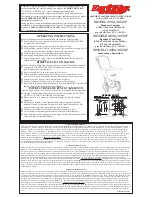
1/4 - 20 Lock-nut
1/4 - 20 x 1-1/2” Bolt
Handle Shaft
Slide
Right
Side
Left
Side
Slide Axle through as shown
1/4-20 x 2-1/4”
Bolt
1/4-20 x 2-1/4”
Bolt
Axle Bearing
Flat
Side
Notch
4.
Install lower handles onto Frame and secure with ¼-20 x 2¼”
bolt through hole in Frame Braces and through the hole in frame
install locknut.
Next, Slide the axle (Coast Wheel side first)
through
the right side lower handle and into the gearbox (with the arrow
facing the
FRONT
), you will need to rotate the axle to engage
with the gearbox, then through the left side lower handle.
TURN SPREADER UPRIGHT ON TO WHEELS.
PAGE 2
8.
Install Handle Shaft as shown below using (2) 1/4-
20 x 1½” Hex Bolt and (2) 1/4-20 Locknuts
5.
Install the bearings over the axle
and press into the notches of the
lower handle as shown above.
Right
Side
DRIVE WHEEL
Left
Side
COAST WHEEL
Slide wheels on axle as shown
33106
1/8" X 3/4" Cotter Pin
33107
1/8" X 1-3/4" Cotter Pin
34103
1" OD. Washer
~~~
IMPORTANT
~~~
Coast
Drive
Upper Handle
1/4 - 20 Lock-nut
1/4 - 20 x 1-1/2” Bolt
6.
Install drive wheel to axle using pin hole nearest to lower
handles as shown. Insert 1¾” Cotter pin through wheel and
through axle. Bend with pliers to prevent pin from falling out.
7.
Install coast wheel to axle using outside pin hole. As shown, add the flat washer, and insert ¾” Cotter pin through axle (not
thru the wheel). Bend with pliers to prevent pin from falling out.
NOW GO BACK AND TIGHTEN ALL NUTS
AND BOLTS, DO NOT OVER TIGHTEN.
9.
Insert (2) 1/4-20 x 1½” Hex Bolt through Gauge and Linkage
Assembly, then through the Upper Handle, Handle Shaft, Upper
Handle and secure with (2) 1/4-20 Locknuts as shown at the right.


