background image

Page 8

MODEL W2265 ONLY

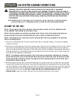
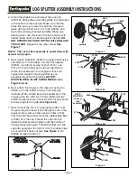
8. Remove the 90 degree street elbow (4122) and the

1” barbed coupler (4160) and insert the street
elbow first into the suction screen (4307) that has
already been assembled into the reservoir. Tighten
the elbow until it faces to the right or engine side of
the log splitter when looking at the log splitter from
the front. Then insert the 1” barbed coupler into the
street elbow and tighten. 

See Figure 4.

9. Assemble the pre-assembled engine assembly onto

the reservoir as shown using four 3/8-16 x 1” bolts
(2102) and four 3/8-16 bi-way locknuts (2104).
Attach the suction hose (4327) between the 1”
barbed coupler and the hydraulic pump (4344)
using two hose clamps (4169). 

See Figure 4.

 Go to

Step 12.

MODEL W2808 ONLY

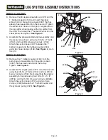
10. Remove the 1” barbed coupler (4160) from the

parts bag and assemble into the suction screen
(4307) that has been installed at the factory.
Tighten. 

See Figure 5.

11. Assemble the engine plate (4371) onto the reservoir

using four 3/8-16 x 1” bolts (2102) and four 3/8-16
bi-way locknuts (2104). Next, assemble the engine
assembly to the plate using four 5/16-18 x 1-1/2”
(48156) and four 5/18-18 bi-way locknuts (60G56).
Attach the suction hose (4372) using two hose
clamps (4169) between the 1” barbed coupler and
the hydraulic pump (4323). 

See Figure 5.

LOG SPLITTER ASSEMBLY INSTRUCTIONS

Figure 4

Figure 5

4122

4160

4327

2102

2104

4307

4169

2102

4344

48156

4323

60G56

2102

4371

4372

4169

4169

4160

4307

2104 (4)

Содержание W2265

Страница 1: ...Includes Models W2265 W2808 Vertical Horizontal LOG SPLITTER Assembly Operating Instructions OM WS2265 04 Rev 030904 Copyright 2004 Ardisam Inc All Rights Reserved Printed in USA...

Страница 2: ...ssed or implied and all other obligations or liabilities on our part Ardisam Inc does not assume and does not authorize any other person to assume for us any liability in connection with the sale of o...

Страница 3: ...t to make any adjustments to the log splitter while the engine is running OPERATING PROCEDURE Never operate the log splitter without guards in place Only operate the log splitter from the operator zon...

Страница 4: ...is hot or running Allow the engine to cool before refueling Never smoke while operating or refueling your log splitter Gas fumes can easily explode Only refuel your log splitter outdoors in a clear a...

Страница 5: ...trates skin and infects blood causing injury gangrene or death Seek emergency medical help at once if injured liquid needs to be removed from tissue Do not reach for or use any skin to check for leaks...

Страница 6: ...seals 4153 two 3 4 ID washers 4159 two 3 4 slotted nuts 4157 and two cotter pins 4155 from the parts bag Remove the wheels 4099 from the crate and place on the ground with the valve stem on the bottom...

Страница 7: ...of the pieces DO NOT OVERTIGHTEN MUST SWING FREELY See Figure 2a 2c 6 Next attach the tongue to the reservoir using two 3 8 16 x 3 bolts 4359 and two 3 8 16 bi way locknuts 2104 Attach travel lock as...

Страница 8: ...e 1 barbed coupler and the hydraulic pump 4344 using two hose clamps 4169 See Figure 4 Go to Step 12 MODEL W2808 ONLY 10 Remove the 1 barbed coupler 4160 from the parts bag and assemble into the sucti...

Страница 9: ...ter 4106 Route the hose over the top of the tongue and under the beam Next remove the inlet hose 4210 for W2265 60 long or 4209 for W2808 48 long and install between the pump outlet and the bottom of...

Страница 10: ...ONS FOR FILLING HYDRAULIC SYSTEM 1 Fill the hydraulic reservoir with at least three gallons of hydraulic fluid After the hydraulic reservoir and the engine crankcase are filled with oil start the engi...

Страница 11: ...log splitter 2 Place a log on the beam against the foot plate Make sure that the log is securely on the foot plate and up against the beam 3 Depress the control valve handle so that the cylinder will...

Страница 12: ...aulic cylinder take special care not to damage the control valve The wedge can now be removed and sharpened 5 Refer to the Repair and Maintenance Safety section of this manual 6 All replacement parts...

Страница 13: ...________________________________________________________ ______________________________________________________________ ______________________________________________________________ _________________...

Страница 14: ...339 4153 4099 4156 4155 4157 4159 4154 48300 2102 2104 4 4322 60G56 2 4321 60G56 4 4327 4169 4344 4364 2 4326 WL38 3 4361 3 4193 4210 4127 4117 WF12 4333 4336 WF12 4137 4105 4155 4155 4359 60G56 4339...

Страница 15: ...6 Kick Stand 1 4307 Suction Screen 3 4 x 1 1 2 x 4 1 Part No Description Qty 4314 Stripper Bar Removable 2 4319 Engine Plate 6 5 hp 1 4321 Mount Adapter Plate Hydraulic Pump 1 4322 Pump Spacer Alum Ex...

Страница 16: ...p Briggs Stratton 4 dia x 24 stroke auto return 2 stage 11 gpm 26 14 seconds 4 00 x 15 high speed road 1 7 8 dia 7 high 6 x 6 3 75 gallons replaceable spin on replaceable in tank screen 70 25 vertical...

Отзывы: