AVS-H-IM (03/13)
Page 5
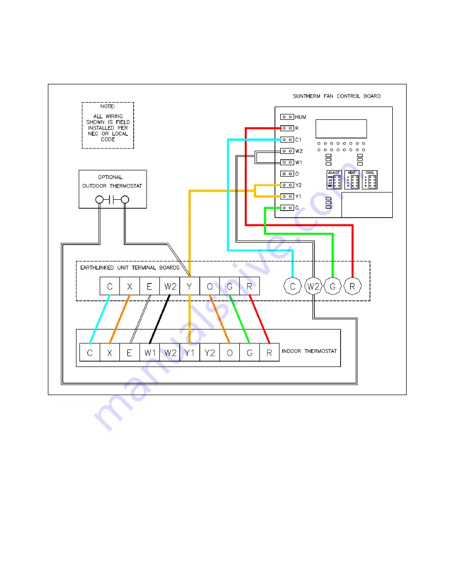
AVS Electrical Connections and Air Flow
The variable speed AVS Series air handler control board and field wiring diagram are illustrated in
Figure 1.
Figure 5. AVS Series Air Handler Control Panel and Field Wiring
The blower speeds can be adjusted by changing the jumper settings on the control board as
appropriate.
Heat and Cool panels:
“A” is the highest speed and “D” is the lowest speed.
Adjust panel:
“NORM” is the normal airflow. “+” is more airflow. “-“ is less airflow.
Test panel:
NOT FOR FIELD ADJUSTMENT. FOR FACTORY USE ONLY.
Содержание AVS - 1824-V
Страница 4: ...AVS H IM 03 13 Page 4 Refrigerant Tube Connections...
Страница 7: ...AVS H IM 03 13 Page 7 AVS Dimensions and Electrical Ratings...
Страница 9: ...AVS H IM 03 13 Page 9...
Страница 10: ...AVS H IM 03 13 Page 10...
Страница 11: ...AVS H IM 03 13 Page 11...
Страница 12: ...AVS H IM 03 13 Page 12...
Страница 13: ...AVS H IM 03 13 Page 13...
Страница 14: ...AVS H IM 03 13 Page 14...
Страница 15: ...AVS H IM 03 13 Page 15...
Страница 16: ...AVS H IM 03 13 Page 16...