SUBJECT
REF. MDL.
REPORT NO.
INSTRUCTIONS FOR CONTINUED AIRWORTHINESS
GA182
ICA182-2
Rev. A
10/15/12
SEE NON-DISCLOSURE NOTICE ON THE COVER PAGE
30 of 101
Copyright 2012
Eagle Copters
All Rights Reserved
5.3
Digital Router Re-Installation
NOTE
The location shown in the aft baggage compartment is shown for reference only. The
exact placement of the components is dependant on the other pre-existing installed
equipment.
NOTE
If the Hat Section Brackets (P/N G13005-1) have not been removed skip to step (c) and
connect to the Router to the mounted Hat Section Brackets. If the Hat Section Brackets
have been replaced continue to step (a).
a.
Before installing new Hat Sections, assemble with G13005-2 Back
Plate to maintain proper spacing. Locate G13005-1 Hat Sections over
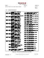
two of the stiffening ribs as shown in Figure 16. Back drill two
mounting holes in bulkhead and Cleco in place. Remove back plate.
b.
For each Hat Section, back drill bulkhead and install 14 #4 Rivets,
MS20470AD4-4 as shown in Figure 16.
c.
Connect the Digital Router (P/N G13000) to the Back Plate (G13005-2)
using 4 MS24693S272 Screws as shown in Figure 16.
d.
Hang the Router/Backplate assembly on the Hat Sections mounted on
the FS168 Bulkhead into the slots. Be sure the Router/Backplate
assembly is seated fully down.
e.
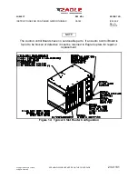
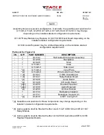
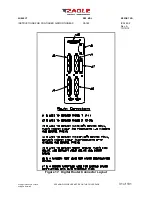
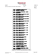
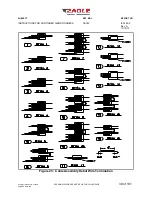
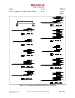
Reconnect all applicable cables to the Digital Router. Reference Figure
17 for all Digital Router Connection Ports.


