


10
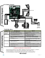
AVI Slide Rev - C
Loops
Entr
apment Protection
+ MAGLOCK
- 24 VDC
#5
+ ALARM
- 12 VDC
#6
REVERSE
LOOP
#2
POWER
24V
AC
#7
KEY
#3
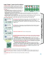
INPUT/OUTPUT
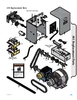
Reverse and Exit In-Ground Loop Installation
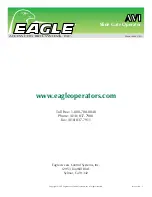
External Entrapment Protection
Reversing loops are used to prevent the gate from closing on a vehicle while it is in the gates path.
A exit loop is used to automatically open the gate when a vehicle approaches to exit.
A phantom loop is
NOT
used for slide gates.
An experienced installer should perform this installation.
Installation of a reversing edge(s) or photocells for the
OPENING
direction of the gate is recommended.
Mount
reversing edge(s)
where needed (end of gate along entire height of gate and/or next to opening on operator side).
Mount
photocells
for entrapment protection during the
OPENING
cycle of gate if needed as shown below (they are typically mounted 21”
above the ground but no higher that 27.5” high).
Multiple
external entrapment devices may be connected in parallel to
#4 M-FCN Input.
Multi-Function switches 1 and 2
MUST
be set to
OFF.
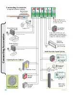
Loop wire must be wrapped inside
the groove three times. Fill the
grooves with a proper sealant.
External Loop Detector
Connect loop wires directly to external loop detector.
See page 16 to wire loop detectors to control board.
Loop feed must have the loop
wires twisted in them approx.
6 twists per foot.
Groove
4’
4’
4’
4’
4’
Reverse Loop
Cutaway of Groove
Loop Feed
Loop
Feed
4’ Min.
4’
4’
4’
Reverse Loop
Exit Loop
1 1/2”
1/4”
Backer Rod
Sealant
Twisted
Loop Wire
Inside
PVC Conduit
Separate
Power
MULTI FUNCTION
1
O
N
2
ON ON STOP N/C
ON OFF CLOSE
OFF ON PHANTOM
OFF OFF EDGE SENSOR
S1 S2 FCN
M-FCN
#4
OFF
Multi-Function switches
Miller
Reversing Edge
Opening Direction
Photocells
Closing Direction
Photocells
CLOSED Gate
OPENING
Direction Edge
OPENING
Direction
Edge
CLOSING
Direction
Edge
OPENING
Direction Photocells
CLOSING
Direction Photocells
Sep
arate
Po
wer
Rec
eiv
er
Trans
mitte
r
Transmi
tte
r
Rec
eiver
Separate
Powe
r
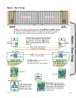
MOTOR 15A
OPENING
TIMER
ERD CONTROL
MULTI FUNCTION
GATE STATUS
FEATURE SELECTOR
1
0
CLOSING
MASTER
OPEN RIGHT
BRAKE ON
CLOSE TIMER ON
SLAVE
OPEN LEFT
BRAKE OFF
CLOSE TIMER OFF
1
ON
2
3
4
OFF—ON
SELECT
OPEN
LIMIT
OPENING CLOSING CLOSED
LIMIT
SLAVE MASTER
+ –
+ –
#9
#8
+ MAGLOCK
- 24 VD
C
#5
+ ALARM
- 12 VD
C
#6
REVERSE
LOOP
#2
POWER
24V
AC
#7
KEY
#3
M-FCN
#4
#1
COMM PORT
INPUT/OUTPUT
1
O
N
2
ON ON STOP N/C
ON OFF CLOSE
OFF ON PHANTOM
OFF OFF EDGE SENSOR
S1 S2 FCN
COMM PORT
POWER
Содержание AVI
Страница 2: ...2 AVI Slide Rev C ...
Страница 23: ...21 AVI Slide Rev C NOTES ...


