MFT-40 DSB Transceiver Kit
Page 12
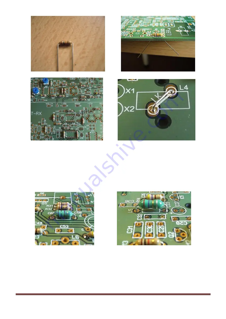
Axial Inductors
L5 and L8
These components look like thick-bodied resistors and the body is colored blue or green. In its interior
there is a small coil wound on a ferrite core. Refer to the parts list to select the correct component for
each location. Mount the inductors in their respective locations, as identified on the circuit board, in the
same manner as you did with the resistors, but leave a separation of 1-1.5mm from the board.
Diodes
Next mount the diodes, being careful to place them with the correct orientation. There is a band on one
end of each diode that corresponds to the component outline on the circuit board.
D1 is 1N4148; it is normally orange in color with a black band and has the type
“4148” printed on the
body.
D3 is 47V zener diode. It is marked as BZX85C47 or Z47.


