Payter Installation Guide
6
10.
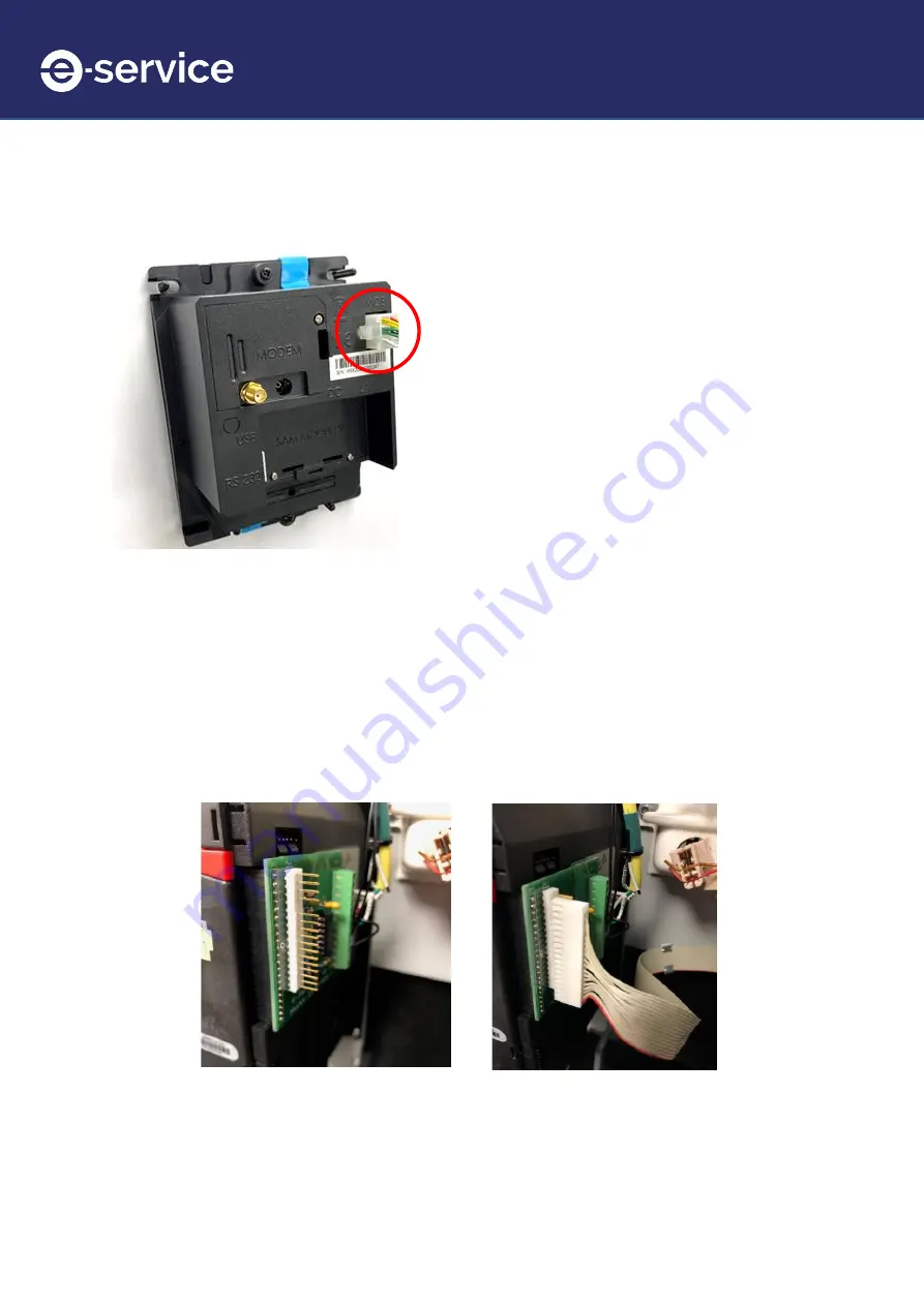
Connect the Payter pulse loom to the Payter device
Connect the white molex plug of the Payter pulse loom to the back of the Payter device,
figure 9, and connect the non-terminated end to Interface board as shown on the
connections page (the last page).
Figure 9
11.
Reinstall the removed inner door hardware
Re-populate the inner door with the hardware taken off the old inner door in part 6,
however use the new coin mech provided.
12.
Plug in the Payter Interface board into the coin mech
As illustrated in figure 10, so that the interface board sits over the back of the coin mech.
13.
Plug the coin mech loom into the board
Plug the loom which was plugged into the coin mech into the interface board header pins.
Skip the first pin on the board header as demonstrated in figure 11.
Figure 11
Figure 10


