background image


 5 

Anchor Screws 

Controls 

Control Wiring

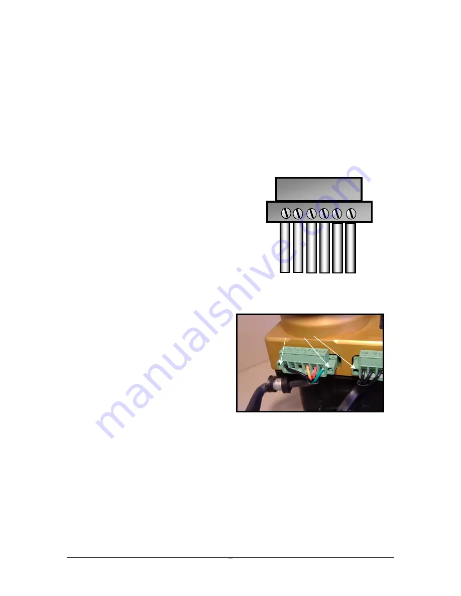
 – Control leads are connected to the ignition via a Control Plug that 

captures each lead with a screw cage mechanism.  The plug is then attached to the 
ignition and secured with anchor screws on either side.   A wiring diagram is included 
at the end of this manual.  The numbering system for the plug terminals is 1 thru 6 as 
viewed looking at the cage screw heads with wires oriented below (see fig). The 
wire/plug assignments are as follows

  Use the cushioned anchor strap to provide a 

mechanical strain relief for the wires. 

1.


“1” connects directly to a nearby 
engine case ground using 18 gauge 
wire.

  Note 1: You cannot rely on the 

ignition’s mechanical attachment to the 
engine to provide ground.  Aluminum 
anodizing acts as an electrical 
insulator, so the clamp connection to 
the anodized flange will not serve as a 
reliable ground.


2.


“2”  Control Alternate (future use)


3.


“3”  Control Alternate (future use)


4.


“4” connects to your ignition 
ON/OFF (ground) p-lead switch 
using 20 gauge wire or larger.


Note 1:  If you are replacing a 
magneto, your old P-Lead can 
serve this purpose, and may 
already be wired to a suitable 
switch.  Note 2:  Non-starting 
magnetos require a mechanism to 
prevent them from firing during 
start-up. Keyed ignition switches 
have a jumper on the back that serves this purpose.  When installing an E-
MAG in place of a non-starting magneto that was controlled by such a 
switch, make sure you remove this jumper. You do NOT want a start-up 
block on any circuit controlling your E-MAG(s).  

5.


“5” connects to your main 12 volt aircraft buss through a dedicated circuit 
breaker (not provided) using 18 gauge wire.  E-MAGs should use a 5-amp 
breaker, and P-MAGs should use a 3-amp switchable breaker.  The 
switch is needed to test the P-MAG  internal alternator during ground run 
up – see Operating Notes. 


Note 1:  Whenever the aircraft buss is 

powered up, the ignition is “awake”.  It draws a small amount of current 

Tack 

1

Control Plug 

5  6 

3
A
L
T

2
A
L
T

Содержание E-113

Страница 1: ...Product Documentation Installation Operating Guide V L113 6 ...

Страница 2: ...uction in our warranty compared to earlier releases This has been done in response to the unexpected impact our previous 3 year warranty was having on our banking and credit card merchant account relationships In lieu of a 3 year warranty we have instituted an extremely lenient policy of service and support for our products covering 3 years or 1000 hours which ever comes first Caution The aircraft...

Страница 3: ...1 T able of Contents OVERVIEW 2 DRIVE GEAR 4 CONTROLS 5 SPARK PLUGS HARNESS 6 INSTALLATION AND TIMING 10 OPERATING NOTES 13 WIRING DIAGRAM 15 CURRENT DRAW 16 ...

Страница 4: ...ing a Attach three four if you use the tack leads to the Control Plug b Spark plugs and the spark plug harness c MAP manifold pressure sensor tube 3 Install your E MAG ignition on the engine set the timing select the maximum timing advance CAUTION Do NOT strike or apply significant inward force to the ignition shaft Doing so could cause it to shift and lose proper position sensor alignment CAUTION...

Страница 5: ...3 make the LED light up Firing the ignition without all connections could damage the unit and void your warranty ...

Страница 6: ...ill be necessary to remove the gear without damaging it or the magneto NEVER strike the magneto or the gear 3 Install the drive gear on the E MAG shaft using the woodruff key washer s castle nut and cotter key provided Your kit includes three washers one thick and two thin The thick washer should always be used The thinner washers can be used as needed to align the hole for the cotter key with the...

Страница 7: ...ate future use 3 3 Control Alternate future use 4 4 connects to your ignition ON OFF ground p lead switch using 20 gauge wire or larger Note 1 If you are replacing a magneto your old P Lead can serve this purpose and may already be wired to a suitable switch Note 2 Non starting magnetos require a mechanism to prevent them from firing during start up Keyed ignition switches have a jumper on the bac...

Страница 8: ...elated to the ignition s primary purpose Due to the variety of instrument options available our ability to support and troubleshoot tack interface issues is limited MAP Sensor Connect one end of the sensor hose to the MAP nipple on the back of the ignition case next to the coil base and secure with nylon clamp Route the line to a convenient connection point connecting hardware not included where y...

Страница 9: ...ectrode Auto Spark Plug Adapters Plug adapters permit the use of 14mm automotive type plugs with a reach Not suitable with engines that use long reach 13 16 aircraft plugs First install adapters with the supplied gasket on the spark plugs finger tight Then insert in engine and tighten to 15 in lb standard plug torque Note If you install and torque the adapters separately stresses will be more focu...

Страница 10: ...leads to the coil and review the wire route You might even install the wire separators if you plan to use them so you can more accurately determine the correct length Cut the plug wire end where it meets the plug tip Install the spark plug boots and terminals Now that you ve had some practice with crimping terminals it may be more convenient to install them with the wires on the engine 4 Crimping ...

Страница 11: ...c Free the terminals from their strips with wire cutters d Fold the wire core back against the shield and position in the crook of the terminal ears and Pre Crimp the terminal Pre Crimping will snug the ears against the wire shield for positioning and point the tips of the ears inward just enough so they fit in the W Crimp slot on the tool e Final Crimp the terminal using the W Crimp slot on the C...

Страница 12: ...ed to the installation and handling of E model and P model E MAG ignition s ONLY If you are installing dual E MAGs pull the breaker AND the coil plug from BOTH ignitions Reconnect them ONLY as instructed and only for the ignition you are working with If you have a companion ignition by another manufacturer BE ADVISED you need to follow all safety and handling guidelines of that system SEPARATE AND...

Страница 13: ...iven situation In general builders with high compression engines or those experimenting with auto fuels might want to use the low advance setting Note 2 Terminals 2 and 3 are an RS232 connection that will enable a number of enhanced communication and control features Watch for future announcements Index Ignition Timing 1 Rotate your prop to the engine TDC or TC timing mark Note 1 It does not matte...

Страница 14: ...stance equal to one tooth width and reinsert the ignition This should get the index GREEN position within your adjustment range 6 Once the GREEN LED is reacquired secure the position by tightening the mounting clips 7 When finished setting the timing for both ignitions and only then you can then reconnect the coil plug to the ignition Confirm Plug Wiring Before running the ignition it s a good pra...

Страница 15: ... puff prior to engine start However in that instance the intake manifold channeled this puff to the sump which was later measured as a 15 to 20 psi pulse This pulse cracked the light weight composite sump installed on the test cell engine An identical replacement sump did the same thing during a second hot start When replaced with a standard aluminum sump the problem did not recur on any subsequen...

Страница 16: ...called upon in an emergency aircraft power failure the P MAG internal alternator will take over automatically There is no need for operator action of any kind Emergency Prop Starting Both the E MAGs and P MAGs need outside electrical power to start You cannot prop start the engine with either ignition if the battery is missing or totally dead However a low battery that barely bumps the starter mot...

Страница 17: ...stomer support Connector Plug viewed from cage screw side Opto Isolator Opto Isolator Inside Case Outside Case Power and ground wiring should be 18 gauge Other wires can be 20 gauge 5 Volts 1 To ground on engine case 1 4 P Lead ignition switch to ground stops ignition firing 4 5 Aircraft Power 13 8vdc through 3 P MAG or 5 E MAG amp breaker 5 6 Optional Tack Output 12 volt pulse 20 millisecond long...

Страница 18: ...ded as an aid to builders for planning their electrical loads under normal operating conditions E MAG Ign Current Map 13 8 nominal voltage 0 00 0 10 0 20 0 30 0 40 0 50 0 60 0 70 0 80 RPM CURRENT E MAG model P MAG model E MAG model 0 09 0 11 0 32 0 16 0 18 0 20 0 31 0 42 0 53 0 65 0 76 P MAG model 0 09 0 11 0 32 0 16 0 17 0 23 0 30 0 15 0 02 0 00 0 00 0 00 0 00 200 00 300 00 400 00 500 00 1000 0 0...

Отзывы: