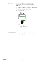
E+E Elektronik EE29 Series Скачать руководство пользователя страница 25

25

CONFIGURATION SOFTWARE

LIMITED LIABILITY

E+E Elektronik

®

is not liable for any damages or consequential damages (for example, but

not restricted to loss of earnings, interruption of business, loss of information and data or
any other pecuniary damages), that result from the installation, usage and also 
impossibility of usage of a software product from E+E Elektronik

®

and supportservices

possibly associated with it or non-performance of support.

1.

GENERAL INFORMATION

The configuration software was developed by E+E Elektronik Ges.m.b.H to allow fast and easy
configuration of individual transmitters (EE29 / EE31) as well as of transmitter networks
(only EE31).

This software tool is included in delivery.
System requirements: MS WINDOWS 98® or higher; RS232 serial interface

2.

INSTALLATION

Insert the CD-ROM supplied with the transmitter into your PC and open the set-up
application. Follow the instructions of the dialogue menus to set the desired language
and all further parameter for installation. At the end of the routine, the software is installed
and the Readme file or the program will be automatically opened. 

Note:
If the configuration software has already been installed, or for upgrade only, the older
version must first be uninstalled (the User will be notified during the installation routine
and the process will be interrupted automatically).

To remove the previous version, open the software folder in the system control panel. All
of the programs installed on your system are located here. Uninstall the EE29/31
Configurator by clicking on the appropriate button and then install the upgrade.

i

Configuration software

Содержание EE29 Series

Страница 1: ...UAL Hardware and Software Hardware and Software Series EE29 EE31 Series EE29 EE31 HUMIDITY TEMPERATURE HUMIDITY TEMPERATURE TRANSMITTER TRANSMITTER BA_EE29_EE31_05_e technical data are subject to chan...

Страница 2: ...used in accordance with the installation manual may cause harmful interference to radio communications However there is no guarantee that interference will not occur in a particular installation If t...

Страница 3: ...tion 11 7 2 2 point temperature calibration 12 7 3 1 point humidity calibration 14 7 4 1 point temperature calibration 15 7 5 Resetting to factory calibration 16 8 MAINTENANCE 17 8 1 Sensor replacemen...

Страница 4: ...ilter cap as the sensor element could be damaged The sensor is an Electro Static Discharge sensitive component ESD When touching the sensor element ESD protective measures should be followed Grip sens...

Страница 5: ...Various options extend the large number of applications The construction of the transmitter enables field calibration and local loop calibration in a simple way 5 3 INSTALLATION Mounting of the housi...

Страница 6: ...lly or vertically pointing downwards When possible a drip sheet should be fitted for each mounting i stainless steel mounting flange bow for draining water of condensation 13 vertical horizontal mount...

Страница 7: ...Rel 2 4 ELECTRICAL CONNECTIONS 1 2 3 4 5 1 2 3 4 5 Description Connection assignment V 5 GND 4 GND 3 OUT1 2 OUT2 1 Description Connection assignment GND Ser 5 Rxd B 3 Txd A 1 not assigned 2 4 Euro St...

Страница 8: ...e removed 3 Fitting of the network chip For refitting to RS485 an IC must be used available as an option The notch on the chip must match the receiver slot 4 Display These pinboards are determined for...

Страница 9: ...hest measured value 1 Select the desired measurand 2 To display the maximum value of the selected measurand press the button for at least five seconds 3 1 To reset the instrument to its normal operati...

Страница 10: ...or high humidity temperature calibration point REL1 REL2 Status Relay ERROR 01 04 see Hardware chapter 8 3 Self diagnosis and error messages 5 MEASURED VALUES from up to units EE31 A F EE31 B EE31 D...

Страница 11: ...Software chapter 5 4 Calibration i i 1 Insert the sensor probe into the reference humidity 1 low calibration point and stabilise for at least 20 minutes 2 BUTTON S2 Pressing the button for 5 seconds s...

Страница 12: ...as hing 10 BUTTON S1 store Pressing the button for 5 seconds stores the calibration value and the procedure is ended LED D2 flashes to indicate exiting of the calibration mode and the symbol CALIB HIG...

Страница 13: ...ation point 6 Insert the sensor probe into the reference temperature 2 high calibration point and stabilise for at least 10 minutes 7 BUTTON S1 Pressing the button for 5 seconds starts the procedure f...

Страница 14: ...re The calibration mode is indicated by the lit LED D2 and the symbol CALIB HIGH will appear on the optional LCD display CP 50 RH or BUTTON S2 Pressing the button for 5 seconds starts the procedure Th...

Страница 15: ...ressing the button for 5 seconds starts the procedure The calibration mode is indicated by the symbol CALIB HIGH on the optional LCD display CP 45 degC or BUTTON S2 Pressing the button for 5 seconds s...

Страница 16: ...seconds starts the procedure for the calibration mode RH Pressing both buttons simultanously for 10 seconds customer calibration settings are reset to factory calibration A short flash of the LED D1 i...

Страница 17: ...Start configuration software on PC 9 For further instructions see Configuration software chapter 5 3 Sensor Probe replacement i active side Transmitters of the EE29 31 xDx and xEx series are availabl...

Страница 18: ...transmitter Reset to factory calibration and repeat the calibration routine Filter soiled Replace filter Sensor defective Replace sensor Output configured incorrectly PC Software Long response time Fi...

Страница 19: ...les external diameter 4mm 2 core twisted pair Typ 50 pF m impedance 100 Ohm non shielded In accordance with the RS485 standard cables in category 5 UTP specified according to EIA TIA ANSI 568 meet the...

Страница 20: ...e following plug connectors are also necessary Y splitter Siemens 6ES7 194 1KA01 0XA0 Plug Lumberg RSC 5 7 RS232 485 Converter To adapt the RS232 interface on the PC to the RS485 network protocol a si...

Страница 21: ...29 31 xEx with 10 m cable for EE29 31 xEx with 20 m cable Replacement sensors Replacement humidity sensor with sensor data Replacement humidity sensor with coating and sensor data Replacement temperat...

Страница 22: ...rature Tf 80 112 0 32 0 32 0 32 degC F Wet bulb temperature Tw 0 32 60 140 80 176 100 212 degC F Water vapour partial pressure e 0 0 200 3 500 7 5 1100 15 mbar psi Mixture ratio r 0 0 425 2900 999 999...

Страница 23: ...pectively 0 10V 1mA IL 1mA 4 20mA RL 500 Ohm 0 20mA RL 500 Ohm General Supply voltage SELV 8 48V DC SELV 12 35V AC SELV Self Electrical Low Voltage Current consumption 2x Voltage output for 24V DC AC...

Страница 24: ...rement accuracy cannot be guaranteed Relative humidity RH Temperature degC Display graphical LCD 128x32 pixels with integrated push buttons for selecting parameters and MIN MAX function Alarm outputs...

Страница 25: ...uirements MS WINDOWS 98 or higher RS232 serial interface 2 INSTALLATION Insert the CD ROM supplied with the transmitter into your PC and open the set up application Follow the instructions of the dial...

Страница 26: ...tree structure only not to the configurations of individual transmitters Therefore only the network structure is saved Transmitters configurations must be reloaded using the command Read All Transmitt...

Страница 27: ...ure requires the input of a number of parameters Group Assigns a transmitter to a group Network The check box network must be selected when several transmitters are operated in a network EE31 series I...

Страница 28: ...will be displayed Other values are shaded and can not be selected or changed Write Writes the current configuration into the selected transmitter Write All Writes the current configuration to all sele...

Страница 29: ...chapter 3 4 Transmitter Delete Transmitter see Configuration Software chapter 3 4 Transmitter 5 INDEX INDEX CARDS 5 1 Analogue For easy configuration of both analogue outputs Range Using the drop dow...

Страница 30: ...High Sets the high switching point Hysteresis Sets the switching hysteresis that should be maintained each time the signal falls below the upper switching threshold Schaltpunkt switching point C kj k...

Страница 31: ...ter 8 1 Sensor Replacement 3 Enter the nominal capacity C76 and the humidity coefficient in the corresponding input fields 4 Save the settings by clicking on the button Save Transmitter Replacement Pr...

Страница 32: ...ate measurement results at a defined working point humidity point For calibration procedure see Hardware chapter 7 Humidity Temperature Calibration 1 Stabilise the probe of the desired humidity for mi...

Страница 33: ...value in the input field Humidity Reading with the reference humidity Value of the saline solution or display of HUMOR 20 8 By clicking on Save the humidity reading of the transmitter will be adjusted...

Страница 34: ...rmation on the date of the last humidity calibration but only where this was performed using the configuration software Note Manual calibration processes performed directly on the circuit board are no...

Страница 35: ...M port serial interface of the PC Notebook in the pull down menu Interface Enter the name for the transmitter in the Name field Complete the New Transmitter process by clicking on the button Add 6 2 H...

Страница 36: ...ce Building No 8 Bei Chen Dong St Chao Yang District Beijing 100101 P R China Tel 86 10 84992361 86 10 84992362 Fax 86 10 84992363 info epluse cn E E FRANCE Les Cr tes Dor es 1 F 69210 Sourcieux les M...

Отзывы: