User Manual EE212
Modular Humidity and Temperature Sensor | 9
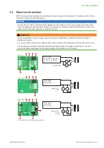
20...30 V DC R
L
<500 Ohm
11...30 V DC R
L
<50 Ohm
Output: 4-20 mA
OUT1
OUT2
Output: 0-5 V
0-10 V
0-20 mA
15...35 V DC
24 V AC ±20 %
V
mA
V
mA
OUT1
OUT2
Output: 0-5 V
0-10 V
15...35 V DC
24 V AC ±20 %
V
V
OUT1
OUT2
EE212-A6
EE212-A2/A3
EE212-A2/A3
1)
EE212-A5
1
2
3
4
5
6
7
1
2
3
4
1
2
3
4
5
5
6
1) When ordered with option D2 (display with backlight)
EE212-J3
Output:
Modbus RTU or
BACnet MS/TP
15...35 V DC
24 V AC ±20 %
8
1
2
3
4
5
6
9
Fig. 1
EE212 connection options
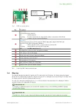
No.
Function
1
Green LED
Information during operation
On
normal operation
Flashing
the main board does not recognize the probe’s measurement electronics
Off
no power supply or main board failure
2
Blue LED
Information during setup with the optional USB configuration adapter HA011066 and
the EE-PCS Product Configuration Software
On
USB connection to PC, no communication with EE-PCS
Flashing
communication with EE-PCS in progress
Off
no USB connection to PC
3
Configuration connector (USB configuration adapter)
4
FFC cable socket for the display
5
Screw terminals for power supply and outputs
6
Screw terminals, do not connect
7
Output signal (I / U) selection
8
Bus termination resistor 120 Ω (jumper)
9
Address DIP switch for RS485 interface
Tab. 1
Parts of the EE212 electronics board types
3.4 Display
The optional display is available for wall mount (T1) and duct mount (T2) types. Per factory setup the display
shows the two measurands selected for output 1 and output 2 for analogue versions (according to ordering code).
For digital output versions the display shows RH and T.
The user can change the display layout to 1, 2 or 3 lines and select the parameters to be displayed. Refer to
chapter 5 Setup and Configuration for details.
PLEASE NOTE
The display is available as spare part, intended for replacement only, not for retrofitting an EE212 originally
ordered without display.
PLEASE NOTE
The EE212 (4 - 20 mA, 2-wire version) with display operates correctly only if both outputs are connected.


