3-23
M O D E L 4 2 4 D Y N O W A R E R T U P G R A D E W I T H E D D Y C U R R E N T B R A K E
Cable Routing
Version 5
DynoWare RT Upgrade for Model 424x Dynamometers Installation Guide
16 Route the speed
pickup/brake cable (F) from the speed pickup card and brake
solenoid leads on the stationary dyno, through the pit conduit (for in ground
dynos), and connect to DRUM 1 on the back of the DynoWare RT module.
Route the speed pickup/brake cable (F) from the cable track, through the pit
conduit (for in ground dynos), and connect to DRUM 2 on the back of the
DynoWare RT module.
17 Route the Linx detect sensor cable (I) from the second cable track, through the pit
conduit (if in ground), and connect to Linx 1 on the back of the DynoWare RT
module.
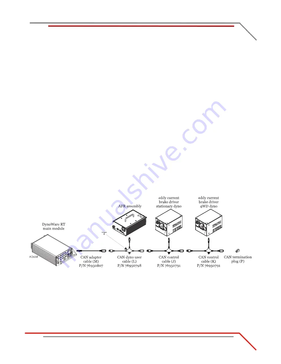
18 Connect the CAN
pendant cable (D) to the DynoWare RT module.
19 Connect the remote atmos cable (C) to the DynoWare RT module.
20 Attach the CAN adapter cable (M) to the back of the DynoWare RT main module.
21 Attach the CAN dyno user cable (L) to the CAN adapter cable (M) and route to the
AFR assembly. Attach the CAN dyno user cable (L) to the AFR assembly.
Note:
The AFR assembly is an optional accessory.
22 Attach the CAN control cable (J) to the “T” on the CAN dyno user cable (L) and
route, through the pit conduit (for in ground dynos), and connect to the eddy
current brake driver on the stationary dyno.
23 Attach the CAN control cable (K), placed in the cable track earlier, to the “T” on
the CAN dyno user cable (J). Attach the CAN control cable (K) to the eddy current
brake driver on the 4WD dyno.
24 Insert the CAN termination plug (P) in the CAN control cable (K).
Note:
If you do not have an eddy current brake or AFR assembly, insert the CAN
termination plug (P) at the end of your CAN network cable chain.
Figure 3-19: CAN Network Cable Configuration


