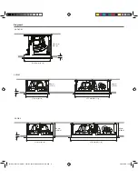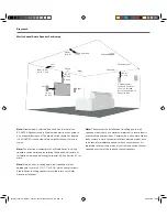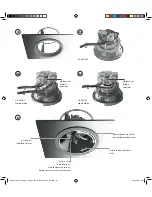
4. In-ceiling Speaker Installation
Note:
These installation instructions broadly assume that speaker
cables are pre-installed in ceilings and walls.
To install a Studio Series in-ceiling speaker, proceed as described
in the following paragraphs and accompanying diagrams:
•
Having selected the installation position and checked for the
presence of studs (joists), pipe work, ducts or cables, mark
a cut-line on the ceiling using the supplied template. Check
that the diameter of the cut-line is correct: 210 mm (8
1
⁄
4
in)
for the S4-C65 and S4-DVC65, and 260 mm (10
1
⁄
4
in) for the
S4-C80.
Use an appropriate tool to cut along the cut-line to create a
cut-out in the ceiling. Trial fit the speaker Installation Frame
in the cut-out to check clearances.
Note:
The orientation of the Installation Frame within the cut-out is
inconsequential.
Note:
If using a pre-construction ring, follow the instructions in the
pre-construction document.
Note:
In order to reduce the possibility of audible ceiling vibration
it may be prudent to apply a bead of adhesive mastic between
the ceiling joists and the drywall (plasterboard) in the vicinity of in-
ceiling speakers.
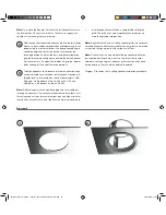
With the ceiling cut-out checked, the Installation Frame can
be installed. Lift the frame into place and while holding it
against the ceiling with one hand use the other hand to turn
the three yellow securing clamps outwards and slide them
down against the inner surface of the drywall (plasterboard).
Note:
If speaker cables are not already installed it should be done
at this stage. It is possible that access will be required through
the floor above to route the cables. Use low resistance speaker
cable with clear polarity marking on its insulation. Low resistance is
especially important if the length of cable from amplifier to speaker
exceeds 5 m. Your local Dynaudio retailer or distributor will be able
to offer advice on speaker cable selection if required.
•
Pull the speaker cable through the Installation Frame and
ceiling cut-out. The length of free cable should be sufficient
to allow the Speaker Unit to be held in one hand while
connecting the cable to the Speaker Unit terminals with the
other hand.
1
2
3
The speaker cable can now be connected to the Speaker Unit.
Strip 15 mm insulation from the cable (if necessary), twist the wire
strands and insert the stripped ends into the appropriate speaker
spring terminals.
If the ceiling speaker is a S4-C65 or S4-C80 model simply
ensure that the positive conductor is connected to the red
speaker terminal and the negative conductor is connected
to the black speaker terminal.
If the speaker is a S4-DVC65 model it can be connected in one of
two modes: Stereo and Mono.
Stereo mode: Stereo mode is appropriate if the S4-
DVC65 is to be connected to stereo left and right amplifier
channels. Connect the positive and negative conductors
from each amplifier channel to one set of red and black
speaker terminals. Ensure that the positive conductors are
connected to red terminals and the negative conductors are
connected to black terminals.
The dipole switch on the rear of the S4-DVC65 model should
be set to Normal.
Mono mode: Mono mode is appropriate if the S4-DVC65
is to be connected to a single amplifier channel for multi-
channel surround applications. Connect the positive
conductor to the left hand red terminal and the negative
conductor to the right hand black terminal. Use a short
length of cable to connect the remaining two terminals
together.
The dipole switch on the rear of the S4-DVC65 model will
change the phase of the left tweeter from 0 degree in normal
to 180 degrees in Dipole. Set the switch to Normal or Dipole
as appropriate.
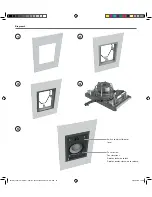
With the Speaker Unit connected to the speaker cable the
unit can be lifted up into the Installation Frame. Turn the
locking tabs on the front surface of the Speaker Unit fully
clockwise (aligned with the lock icons) and insert it into the
Installation Frame. Push gently around each locking tab until
a click is heard. The Speaker Unit will then be secure in the
frame.
Note:
Take care that the speaker cable is positioned in such a way
that it will not get trapped as the Speaker Unit is secured into the
Installation Frame and is not touching the Speaker Unit in such a
manner that it is likely to result in audible vibrations.
4a
4b
4c
5
2018 Dynaudio CI manual - Item No. 307001016932 Rev N - EN.indd 11
05/01/2018 12.39

