


dynaTron solarIs® Plus PhysICal feaTures
DYNATRON SOLARIS
®
PLUS SERIES | SERVICE MANUAL REV. 6 | AUGUST 29, 2017
13
• Check to be sure the snap adapters haven’t fallen off or that the lead wire has not become disconnected from the
electrodes or the device.
• Make sure carbon electrodes have a secure connection with the pin ends of the leads. Over time the carbon
electrodes may become too loose to use safely and the electrodes must be replaced.
• Check for corrosion on lead ends.
• Make sure carbon electrodes are adequately moistened and free from build-up to allow complete contact across
the surface of the electrode.
• Observe the electrode placement. Some areas of the patient’s body conduct current better than others. In areas
where resistance is high you may be unable to obtain optimum conductivity.
• Check the dryness of the patient’s skin. Dry skin does not conduct current well.
• Check to see if the electrodes do not adhere properly when a patient shifts position during a treatment. Worn
electrodes could become loose and a significant change in conductance could result.
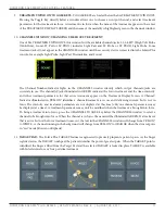
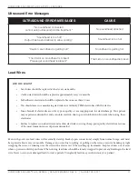
Temperature.
The Solaris Plus devices continuously measure temperature during a Light Probe, Light Pad, Ultrasound, and Combo
Treatment. TEMPERATURE is indicated by the length of the Blue/Green indicator lights on the temperature bar.
The longer the length of the colored bar, the higher the temperature. It is not uncommon to have the temperature bar
move into the medium length ranges. If the temperature of an ultrasound treatment approaches the maximum level
of 108° Fahrenheit (42.22° Celsius), the treatment is automatically PAUSED, output power stopped, and treatment
time stops counting down. Following a cooling period, the treatment may be continued by pressing START.
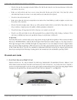
Channels and Jacks
13. Front Panel Channels and High Volt Jack
Illustrated below are the output channels for delivering Interferential, Premodulated, Russian, Biphasic, and
Microcurrent treatments. These channels are located on the front of the device. As you face the device, channels 1
and 2 are on the left, channels 3 and 4 are on the right with the dedicated High Volt jack for delivering High Volt Pad
treatments in the middle. Three channel units (708 and 705) have channels 1, 2, and High Volt.
Front Panel Channels and Jack


