w w w . g o d y n a m i x . c o m
User Manual
5
Chapter 3
Device Appearance and Descripiton
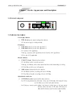
3.1 Device front panel
ETH
E1
PWR
L/R
LOS
TX
RX
LNK/ACT
100M
LAL
RAL
3.2 Indicator description
Power supply indicator:
¾
PWR (Green)
: power supply working status indicator
ON
: the power supply is working normally
E1 indicator:
¾
LOS1 (Red)
: indicator for loss of E1 signal at E1 1
¾
LOS2 (Red)
: indicator for loss of E1 signal at E1 2
ON
: local loss of E1 signal alarm
Flickering
: remote loss of E1 signal alarm, but no local loss of E1 signal alarm
OFF
: no loss of E1 signal alarm
Ethernet indicator:
¾
LNK/ACT (Green)
: Ethernet interface indicator
ON
: the Ethernet cable is correctly connected
Flickering
: the Ethernet cable is well connected and there is data transmitting or receiving
OFF
: the Ethernet cable is not well connected.
¾
100M (Green)
: Ethernet interface rate indicator
ON
: the Ethernet interface is working at the rate of 100Mbps
OFF
: the Ethernet interface is working at the rate of 10Mbps
Optical interface indicator:
¾
ALM/LPR (two-color)
: optical interface alarm indicator
Red ON
: local optical interface total alarm, at lease one of LOS alarm, LOF alarm, E-3 alarm
and E-6 alarm occurs at the local optical interface
Red Flickering
: remote optical interface total alarm, no alarm occurs at the local optical
interface while at least one of LOS alarm, LOF alarm, E-3
alarm and E-6 alarm occurs at the remote optical interface.


