Dynamic Mounting Up and Over Manual Mount Скачать руководство пользователя страница 13

Install Video at 

www.DynamicMounting.com/Install


13 

13 

Setting the Tilt 

In  the  top  position  the  mount  tilts  from  vertical  to  about  7  degrees 
(Figure  4 and Figure  5).  To set the angle, put the  mount in the Out 
Position for easier access and so there isn’t any force on the cam.   


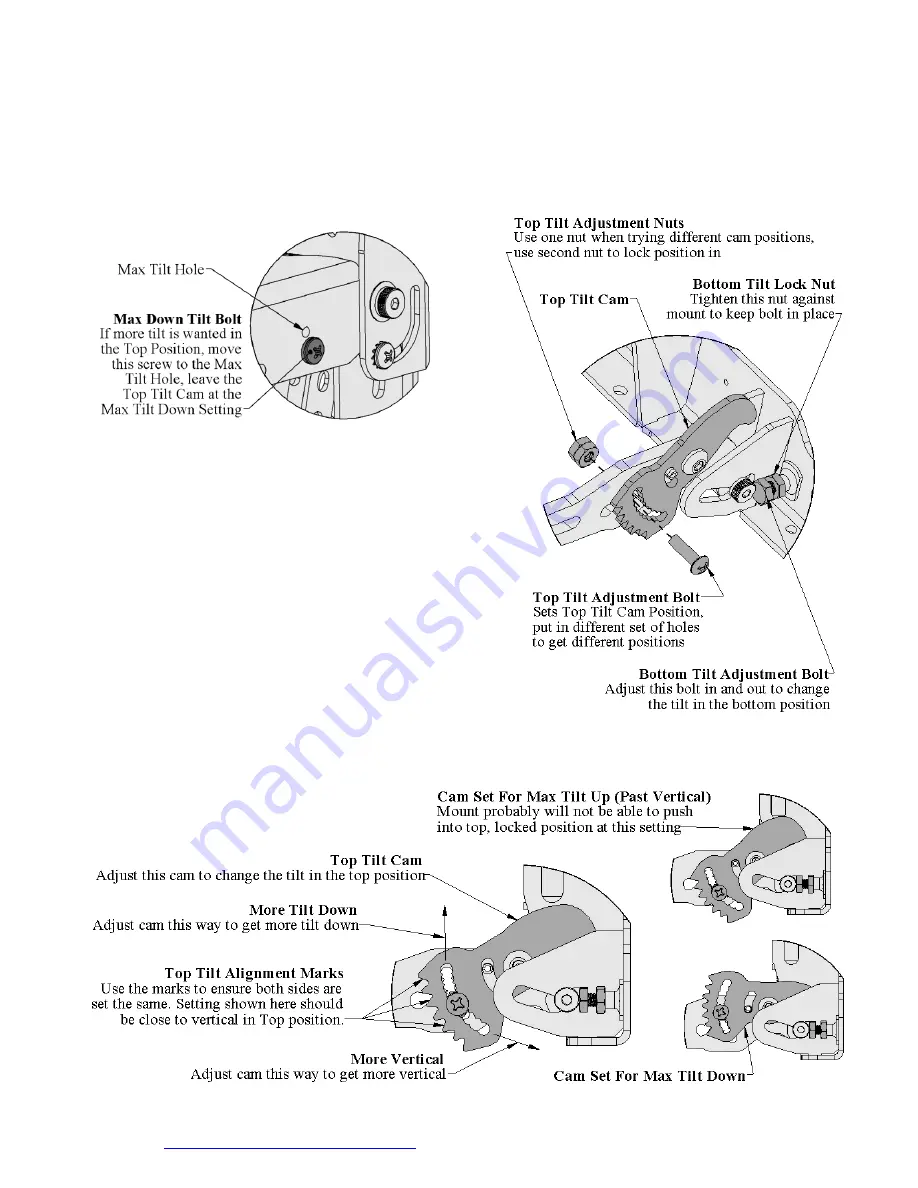
Maximum Down Tilt in Top Position 

The  cam  is  set  for  Max  Down  Tilt  out  of  the  box,  if  more  tilt  is 
required adjust the Max Down Tilt Bolt to the Max Tilt Hole Shown 
in Figure 17.  


Figure 17, Max Down Tilt Bolt and Hole 

(Detail from Figure 2) 


Vertical Tilt in the Top Position 

1.


The Max Down Tilt Bolt (Figure 17) comes out of the box in the 
Vertical Tilt Hole 

2.


Adjust  the  Top  Tilt  Cam  by  removing  the  top  Tilt  Adjustment 
Bolt (Figure 18)  

3.


Put the bolt into a different set of holes and hand tighten with one 
nut. Approximate tilt settings are shown in Figure 19. There is a 
cam  on  both  sides  of  the  mount,  use  the  Top  Tilt  Alignment 
Marks and holes to ensure they are at the same position.   

4.


Move the mount up and see if the tilt is correct, if not change the 
position of the cams, it will probably take a few times to get the 
tilt perfect.  If you get a lot of resistance when trying to push the 
mount to the Top position, the Cam is set for too much up tilt and 
you will need to lessen it.  

5.


Once  you  have  the  desired  position,  tighten  both  nuts  with  a 
7/16“ box wrench and Philips screwdriver.  

Tilt in the Bottom and Out Positions 

In  the  bottom  and  out  position  the  mounts  tilt  can  be  set 
Ve/-1 degree. To adjust, loosen up the 2 Bottom Tilt 
Lock  Nuts  with  a  7/16”  box  wrench.    Next  move  the  2 
Bottom Tilt Adjustment Bolts in and out with the 7/16” box 
wrench  until  the  mount  is  at  the  desired  tilt,  lock  down  the 
locknuts when satisfied with the tilt.


Figure 18, Tilt Adjust Hardware 

(Detail from Figure 2)


Figure 19, Top Tilt Cam Settings (Detail from Figure 2) 

Содержание Up and Over Manual Mount

Страница 1: ...ition examine Figure 1 and Figure 3 to ensure mount is oriented correctly Specifications Fits most Flat and Curved Televisions 40 inches and larger to 120 lbs with Frame 70 lbs as Single Stud No Frame...

Страница 2: ...tall plastic spacers 4 Steel M6 washers Fasteners for Attaching Swiveling Hook Plate Swivel Version Only Assembled on the Left or Right Swivel Setting remove if different setting needed 1 5 16 diamet...

Страница 3: ...te Figure 1 and Figure 3 Show the Mount in the Bottom Position Figure 1 Mount Overall Size With Frame Television Mounting Hole Pattern Range Wall Mounting Hole Pattern Range Note Mount Only Comes with...

Страница 4: ...Frame Television Mounting Hole Pattern Range Wall Mounting Hole Pattern Range Note Mount Only Comes with 2 television Mounting Arms Not the 4 Shown Figure 4 Vertical in Top Position Vertical toleranc...

Страница 5: ...ivel settings which are shown in Figure 5 Max Tilt 7 Degrees in Top Position Each setting has its own advantages The Center Swivel gives you a lot of travel in each direction but has the thickest prof...

Страница 6: ...ench on the top and bottom until all the parts are compressed together and the Swivel Hook Plate takes a little effort to turn you can adjust this effort after the TV is mounted on the wall Figure 6 S...

Страница 7: ...st fitting on the ground 3 If attaching a soundbar lay that out also with the soundbar bracket 4 Figure 9 shows the important things to look for and measure 5 Figure 1 and Figure 3 show important dime...

Страница 8: ...ould be centered on the mount if not the television will sag to one side The heavier the TV and the more off center the more unlevel the TV will be through its range of motion 2 Mark the locations of...

Страница 9: ...s If the wall isn t sturdy enough then more support will need to be added consult an expert 4 The mount must be securely fastened to a structure that can support 4 times the total weight of the televi...

Страница 10: ...sen the 10 Washer and Screw in the TV Hanger 4 Move the Level Bolt Down Until Level 5 Lock Position with the Level Locknut 6 Tighten 10 Washer and Screw back down Figure 13 TV Level Fine Tuning Detail...

Страница 11: ...ably have to push down on the TV to get it into the bottom position Under Ledge Mounting When mounting under a ledge there needs to be enough clearance between the TV and the ledge to ensure they will...

Страница 12: ...ance block settings for various television weights are shown in Figure 16 In Figure 16 the counterbalance is approximately set for a 65 Pound Television To be able to move the mount without a TV on it...

Страница 13: ...shown in Figure 19 There is a cam on both sides of the mount use the Top Tilt Alignment Marks and holes to ensure they are at the same position 4 Move the mount up and see if the tilt is correct if no...

Страница 14: ...t though Wire Management Figure 20 Shows the suggested wire route to keep the wires hidden with maximum flexibility and free from pinching The Cable Loop is black cord loop used to keep the wires in t...

Страница 15: ...tic Retain Washer 4 10 Nut Figure 22 Side View of Handle Hidden Figure 23 Side View of Handle Shown Handle Install Figure 24 shows how to install the Handle We recommend laying everything out on the g...

Страница 16: ...if the mount is modified in any way or not installed correctly including overloading abuse or use for any purpose other than specified in our directions The Limited Lifetime Warranty is for indoor use...

Отзывы: