


Embedded Solutions
Page 17 of 37
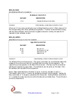
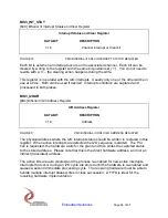
BIS3_IO_MUX
[$1C] BiSerial III Mux Port read/write
Multiplexor Control Port
DATA BIT
DESCRIPTION
31-0
Parallel Port Mux Control bits
FIGURE 9
PMC BISERIAL-III SDLC MUX CONTROL PORT
When set (
‘1’) the corresponding bit is set to State-Machine control. When cleared (‘0’)
the corresponding bit is set to parallel port operation. The Mux control definition along
with the Data, Direction and Termination registers allows for a bit-by-bit selection of
operation under software control.
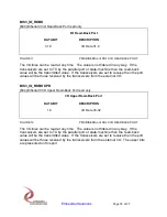
BIS3_IO_UCNTL
[$20] BiSerial III Upper Control Port read/write
Upper Bits Control Port
DATA BIT
DESCRIPTION
25-24
Mux 33, 32
17-16
Termination 33, 32
9-8
Direction 33, 32
1-0
Data 32, 32
FIGURE 10
PMC BISERIAL-III SDLC UPPER CONTROL PORT
The BiSerial III has 34 transceivers. The upper control bits are concentrated within this
register to cover the top 2 bits not controlled within the other control registers. The
upper bits are only useable on the Bezel I/O connector. Pn4 has only 64 connections
and
doesn’t support the upper lines. The definitions are the same as the Data, Term,
Dir and Mux port definitions for bit operation.
Data = Data transmitted when the Mux is set to ‘0’ and the direction is set to ‘1’.
Termination when set to ‘1’ causes the parallel termination to be engaged. Setting the
Mux control bits to ‘0’ creates a parallel port for those bits. Setting the Mux control bits
to ‘1’ enables the state-machine to control the direction and data lines. The termination
control is independent.


