Dynaflite CHIPMUNK Скачать руководство пользователя страница 38

arm onto the servos and the servo cords are
securely connected to the receiver. If you are
not thoroughly familiar with R/C models, ask an
experienced modeler to inspect your radio
installation and make sure the control surfaces
respond correctly.

The engine must be "broken-in" according to
the engine manufacturer's recommendations
for break-in. Refer to the Engine Safety

Precautions on the next page before you start

your engine. After you run the engine on the

model make sure all screws remain tight, the
hinges are secure and the prop is on tight.

AT  THE  FLYING SITE

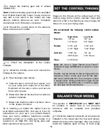
Range Check Your Radio
Check the operational range of the radio before

the first flight of each day. Before you turn your

radio on, the first thing you always must do is
make sure no one else is on your frequency
(channel). Most model flying fields utilize

frequency control so familiarize yourself with
their system. Collapse your transmitter antenna

and turn on the transmitter first, then the

receiver (preferably the receiver should never
be on by itself). You should be able to walk at
least 100 feet away from the model and still

have control. Have an assistant stand by your

model and tell you what the control surfaces

are doing while you operate them from the

transmitter.

Repeat this test with an assistant holding the
model and the engine running at various

speeds. If the control surfaces do not always

respond correctly, do not fly! Find and correct

the problem first. Look for loose servo
connections or corrosion, loose fasteners that

may cause vibration, a defective on/off switch,
low battery voltage or a defective cell, a damaged
receiver antenna or a receiver crystal that may
have been damaged from a previous crash.

Note: Failure to follow these safety precautions
may result in severe injury to yourself and others.

Store model fuel in a safe place away from high

heat, sparks or flames. Do not smoke near the

engine or fuel as it is very flammable. Engine
exhaust gives off a great deal of deadly carbon

monoxide so do not run the engine in a closed
room or garage.

Get help from an experienced modeler when

you learn to operate engines.

Use safety glasses when you operate model
engines.

Do not run the engine near loose gravel or

sand; the propeller may throw loose material in
your face or eyes.

When you start and run the engine keep your
face and body as well as all spectators away
from the plane of rotation of the propeller.

Always be aware and very conscious of hand

movements and be deliberate in your reach for

the needle valve, glow plug clip, or other items

near a spinning propeller.

Keep loose clothing, shirt sleeves, ties, scarfs,
long hair or loose objects away from the prop.
Be conscious of pencils, screwdrivers or other

objects that may fall out of your shirt or jacket
pockets.

Use a "chicken stick" or electric starter and

follow the instructions to start your engine.

Make certain the glow plug clip or connector is

secure so that it will not pop off or get into the

running propeller.

Ask an assistant to hold the model from the rear
while you start the engine and operate the
controls.

38

Содержание CHIPMUNK

Страница 1: ...ed the original cost of the purchased kit Further Dynaflite reserves the right to change or modify this warranty without notice In that Dynaflite has no control over the final assembly or material used for final assembly no liability shall be assumed nor accepted for any damage resulting from the use by the user of the final user assembled product By the act of using the user assembled product the...

Страница 2: ...f this model we assume you have built several models and have a general working knowledge of modeling and its terms If you HAVE NOT built and flown several kits do yourself a favor back up and get some experience before beginning this kit 1 You must build the plane according to the plan and instructions Do not alter or modify the model as doing so may result in an unsafe or unflyable model In a fe...

Страница 3: ...es qualified instructors You can also contact the Academy of Model Aeronautics AMA which has more than 2 500 chartered clubs across the country We recommend you join the AMA which will insure you at AMA club sites and events AMA Membership is required at chartered club fields where qualified flight instructors are available Contact the AMA at the address or toll free phone number below Please insp...

Страница 4: ... Rolls Paint for Fuelproofing and Painting the Engine Cowl and the Canopy Dor 2 1 5 Scale Pilot s 1 4 Latex Foam Rubber HCAQ1000 19 Heavy Duty Hinges Twenty Seven with flaps ROBQ2510 All Pushrods and Control Hardware 5 4 40 Metal Solder Clevis Seven with Flaps GPMQ3814 5 4 40 Hex Nuts Seven with Flaps GPMQ3304 2 4 40 x 12 Wire Pushrod Threaded One End Four with Flaps GPMQ3752 3 4 40 x 48 Pushrods ...

Страница 5: ...ent viscosities of CA s intended for different conditions you will encounter when you build Thin CA is great for tack gluing for glue joints that fit well and for parts that are already joined but need to be permanently bonded Medium CA is used for general construction where you apply glue to one part then join it to another part Thick CA is great for glue joints that don t fit perfectly or parts ...

Страница 6: ...calls for another type of adhesive Aliphatic Resin Resin glues require that parts be pinned or clamped together while the glue dries typically 15 30 minutes Resin glues are very strong and work well with balsa and plywoods Epoxy Epoxy glues are the strongest but require the most time to cure Six minute epoxy cures the fastest it sets within six minutes but is not fully cured for one hour or more T...

Страница 7: ...shows the location of the die cut parts for the wing Not all parts are marked on the die sheets Be sure to mark all parts with a ball point pen prior to removing them from the die sheets 2 REQ 1 8 X 5 3 8 X 20 5 8 PLY CHPGW04 2 REQ 3 32 X 3 X 18 BALSA CHPGW03A 2 REQ 3 32 X 3 X 30 BALSA CHPGW03 2 REQ 3 32 X 3 X 30 BALSA CHPGW02 2 REQ 3 32 X 3 X 30 BALSA CHPGW01 2 REQ 3 32 X 3 X 30 BALSA 7 ...

Страница 8: ...GF02 1 REQ 1 8 X 6 3 8 X 25 1 4 PLY CHPGF01 2 REQ TOP DECK FUSELAGE SIDE CONTROL HORN MOUNTS 1 8 X 6 3 8 X 25 1 4 PLY Note This page shows the location of the die cut parts for the fuselage Not all parts are marked on the die sheets Be sure to mark all parts with a ball point pen prior to removing them from the die sheets 8 ...

Страница 9: ...from 1 8 x 1 2 x 30 balsa Cut the longer ribs first When satisfied with the fit glue them into position Ql 8 Sand the trailing edge of the stab flat as shown on the cross section of the plan Rough sand the stab to the shape shown I I 9 Mark the centerline on the rear edge of the TE along its entire length l l 5 Cut and shape the tips from 1 2 x 3 4 x 12 balsa using the plans as a guide Glue and pi...

Страница 10: ...bs fit the LE andTE well It is not important that each rib fit the exact location shown on the plan Q 16 Notch the LE of both elevators where shown on the plan and fit and glue the die cut 1 8 ply horn bases into place Q 17 Remove the elevators from the plan and rough sand them to the shape shown in the cross section Use care not to gouge the ribs Q 18 Mark the centerline of the elevator leading e...

Страница 11: ...pin them in place on the plan using some leftover 1 16 balsa shims where shown Q 12 The rudder trailing edge is built from two laminations of die cut 1 8 balsa pieces for a total thickness of 1 4 Build two of these assemblies using the plan as a reference Q 13 Cut some shims from leftover 1 8 balsa and place them in position over the plan at the TE where shown Pin and glue the TE into position Q 1...

Страница 12: ... on your workbench and cover it with Plan Protector from bulkhead D aft Begin construction by building the right rear side structure l t Q 5 Using two 1 4 x 15 16 x 36 balsa sticks cut and fit the rear side longerons Pin and glue the parts into position Note The top longeron ends at the leading edge of the stab A separate 1 4 x 15 16 x 5 9 16 stab mount is glued to the rear of the top longeron 1 8...

Страница 13: ...s for the two joints from 1 8 x 1 4 x 30 balsa When satisfied with the fit glue the ply front and doublers to the fuse rear with 6 minute epoxy Q 9 The left fuselage side is built over the right side Remove the right side from your building board and turn it over Use the leftover 1 8 x 1 4 stick to shim the forward ply side Cover the side with Plan Protector Follow steps 5 6 and 8 to build the lef...

Страница 14: ...plan Align the center mark on each bulkhead with the centerline on the plan Sight down from above the fuselage to double check the alignment When you are satisfied that everything is aligned properly glue bulkheads F H and J to the fuselage sides Q 17 Use the 1 4 x 1 4 x30 balsa stick to glue a cross brace between bulkhead D and F and between F and H This bracing will make the tail more rigid Q 13...

Страница 15: ...cks are glued to the bottom longeron at an angle to conform to the curve on bottom formers HTW and JTW Sand the blocks as needed for this angle and glue them to the bottom longeron Q 24 Glue the die cut 1 8 ply tailwheel mount into position on these blocks Glue the die cut 1 8 ply former JTW to the rear of this assembly Glue a piece of 1 8 x 1 4 basswood stringer between JTW and J Q 25 Remove the ...

Страница 16: ...your engine mount Be sure to install any blind nuts required to bolt your engine mount to the spacers Q 29 Glue the die cut 1 8 ply and balsa side bulkhead formers A B C D E F G and H into position on both sides of the fuselage The flat end of A and B goes towards the bottom of the fuselage The flat end of the rest of the formers goes towards the top of the fuselage E and F can be glued on either ...

Страница 17: ...e lower side longeron will need to be carved out in the area where the pushrod clevis will connect to the rudder torque rod horn Q 34 Cut a 1 8 x 1 4 x 31 basswood stringer to length and glue into place to top formers AT BT and IP Do the same for the two CT top formers Use the remainder of the 1 8 x 1 4 x 31 stringer used on the bottom formers Q 35 Glue the die cut 1 8 piy and balsa top bulkhead f...

Страница 18: ...orm to the 6 dihedral angle of the wing Note There is a small section of sheeting that needs to be added at bulkhead D This will be added later when the fuselage bottom is sheeted D 38 Make and glue a second balsa sheet to the right fuselage side Q 39 Using some leftover 1 8 balsa sheeting cut fit and glue filler strips between the sheeting you just added and the fuselage top deck You only need to...

Страница 19: ...nge and then join them with aliphatic resin glue Sand the best side smooth with 150 grit sandpaper U U 3 Pin the 1 4 x 3 8 x 44 basswood lower spar over the plan l l t l 4 Pin a 1 4 x3 8 x 44 basswood stick on the dashed lines called shim stick This will hold the rear of the ribs at the proper angle until there are enough pieces to hold the wing rigid Save the shim stick for later use Q 5 Punch th...

Страница 20: ...t a 1 4 x 3 4 x 24 balsa stick to the correct length and glue it to the rear ofW8 W12 The tip end is glued to the side of W12 Glue the top flush with the top edges of the ribs The stick extends midway between W7 andW8 Q Q 11 Cut a 1 4 x 7 8 x 30 balsa stick to the correct length and glue it to the rear ofW2 W8 The root end is glued to the side ofW2 The tip end glues to the side ofW8 and the front ...

Страница 21: ...first Trim and sand the sheet to fit between the two ribs Sand the bottom edge of the sheet to fit the angle of the lower spar then mark and cut the sheet to the proper height Continue cutting trimming sanding and gluing the sheet for all of the webbing Be sure to remove any pins that will be hidden by the webbing before gluing it into position Q Q 17 Glue a 3 32 x 15 16 x 24 balsa TE sheet to the...

Страница 22: ...cap strips on the tops of ribsW4 W12 Cut the longer pieces first Q Q 25 Check the fit of the 1 2 x 1 x 8 1 2 maple landing gear rail in ribsW2 W3 andW4 When satisfied with the fit glue it in place with 30 minute epoxy Ul Q 21 After the glue has fully dried remove the wing from the building board Q Q 22 Carve and sand theTE and LE to blend with the bottom of the ribs as you did in steps 15 and 18 Q...

Страница 23: ...W1 to W7 and is trimmed at an angle Use your straightedge to keep W1 straight Q Q 29 Glue a 3 32 x 15 16 x 24 balsaTE sheet to the bottom of the outer TE and ribs using aliphatic glue Note that the sheeting extends from W7 to W12 and is trimmed at an angle Q Q 30 Trim theTE sheeting even with ribsW1 andW12 Q 31 Return to step one and assemble the left wing panel Q 2 Test fit the die cut 1 16 ply d...

Страница 24: ...greatly increases the strength of the joint but it is a bit harder to install this way Do not sheet the bottom center section at this time Q 6 Glue the die cut 1 8 ply LE doublers to the rear of the LE between W1 andW2 on both wing panels 1 7 Drill two 5 16 holes through the wing LE and doubler where shown on the plan and in the photo Q 8 Cut two 1 4 x 7 8 x 7 8 balsa blocks from leftover sticks a...

Страница 25: ... and glue these pieces into place spacing the rails to fit the servo you will be using Position the rails so the top of the servo will protrude below the wing the desired amount Q Q 16 Sheet the area around the servo using leftover 3 32 x 3 balsa This gives the covering a place to adhere to Oil 17 Ifyou are installing flaps on your Chipmunk build the flap servo mount between ribsW4 and W5 as you d...

Страница 26: ... will mount Q Q 6 Cut and glue hinge blocks into position from the 1 4 x 1 2 balsa Q Q 7 Remove the aileron from the plan Carve and sand the top of the LE to match the contour of the ribs Taper theTE as well Be careful as it is easy to sand into the ribs Ul t 1 1 Cover the right wing panel with Plan Protector Cut the bottom LE sheet from 3 32 x 1 2 x 24 balsa and pin it to the plan Q Q 2 Cut the b...

Страница 27: ...from 1 4 x 7 8 x 24 balsa Sand the bottom of the LE to match the angle of the flap ribs at their LE Glue and pin it to the 3 32 x 1 2 LE sheet Q Q 4 Glue ribs F2 F7 into place Note that there are two F7 ribs Ql Q 5 From a 1 4 x 1 2 x 36 balsa stick cut and glue two horn reinforcement blocks where the flap horn will mount Q Ql 6 Cut and glue hinge blocks into position from 1 4 x 1 2 balsa Q Q 8 Glu...

Страница 28: ... FLAP FLAP TRIM ALONG LINE FROMFLAPCORNERS Q 1 Mount and align the wing with the fuselage see step 2 The center TE sheeting that was added earlier will need to be trimmed where it extends past bulkhead DB Lightly mark the outline of the fuselage on the top of the wing Now mark the location of the front of former DB on the wing Remove the wing from the fuselage Draw a line on the top of the wing co...

Страница 29: ...e of the wing where it fits to DB CAUTION Read and study steps 1 5 before doing anything Q 9 Use leftover 1 8 ply to make a bulkhead for where the leading edge of the wing meets the fuselage First fit it to the bottom surface of the wing then use a pencil to draw the outline where it meets the fuselage Now trim this bulkhead to shape allowing for the 3 32 sheeting that will be used to fair the win...

Страница 30: ... them together and sand them flat and smooth Make two skins one for each side Our favorite technique is to fit the individual sheets and then glue them together flat on your building board to form a skin You can then sand the skin flat and smooth before it is glued into position This requires a bit of finesse when gluing the skin into place Use a mix of water and rubbing alcohol to allow the skin ...

Страница 31: ...sembly to the ply tailwheel mount with 4 x 3 8 sheet metal screws Q 10 From the top of the fuselage install and connect the rudder pushrod between the rudder horn and servo Make sure you install a clevis retainer and have the linkage properly adjusted as there is no access to this area after you finish this section Refer to the plans for the proper installation of the rudder linkage Note Our proto...

Страница 32: ... bottom of the rudder Glue it into position and then fill in and blend any areas that need it with leftover wood and hobby filler Q 16 Fit the stab into position and adjust the stab mount as needed to make the stab parallel with the wing Be careful not to change the incidence angle of the stab Put a pin in the nose of the fuselage on the centerline Use your string to align the stab just as you did...

Страница 33: ...d cut an opening in it to fit your engine Remove the engine install the cowl and transfer the cutout to the cowl If you go slowly and remove a little material each time from the cowl you will be rewarded with a good looking cowl Q 4 When you are satisfied with the fit of the cowl remove it and glue the four 1 2 x 1 2 x 3 4 hardwood blocks into place on the firewall Sand them to blend to the curve ...

Страница 34: ...vers of balsa wood from the hinge slots with a hobby knife after you drill the holes TEMPORARY PIN TO KEEP HINGE CENTERED AFTER you have completely covered and finished you model perform the following A Use your hobby knife and a sharp 11 blade to remove a small strip of covering from the hinge slots to expose them C Join the elevator to the stab with the hinges If the hinges will not stay centere...

Страница 35: ...model Ul 3 Cover the model We used Top Flite Super MonoKote on the prototype model For the primary white color TOPQ0204 we used two six foot rolls for the wing and one six foot roll for the fuselage We used one can of Top Flite LustreKote Missile Red TOPR7201 paint sprayed directly on the white MonoKote For the black anti glare area in front of the canopy we used some flat black TOPQ0508 we had le...

Страница 36: ...MA R C club flying sites and AMA sanctioned flying events Measure the throws at the widest part of the trailing edge of the rudder elevator flaps and ailerons After a few flights you may change the throws to suit your flying style We recommend the following control surface throws We recommend the following control surface throws Elevator High Rate 1 2 Up Low Rate 3 8 Up 1 3 4 Left 1 3 4 Right 1 2 ...

Страница 37: ...ted this is the time to balance it laterally side to side Here s how Q 1 With the wing level and attached to the model and the engine and muffler installed lift the model by the propeller shaft and the fin thismayrequireanassistant Dothisseveraltimes t 1 2 The wing that consistently drops indicates the heavy side Balance the model by adding weight to the other wing tip An airplane that is laterall...

Страница 38: ...st Look for loose servo connections or corrosion loose fasteners that may cause vibration a defective on off switch low battery voltage or a defective cell a damaged receiver antenna or a receiver crystal that may have been damaged from a previous crash Note Failure to follow these safety precautions may result in severe injury to yourself and others Store model fuel in a safe place away from high...

Страница 39: ...identified with my name and address orAMA number on or in the model 9 I will not operate models with pyrotechnics any device that explodes burns or propels a projectile of any kind RADIO CONTROL 1 I will have completed a successful radio equipment ground check before the first flight of a new or repaired model 2 I will not fly my model aircraft in the presence of spectators until I become a qualif...

Страница 40: ...sport models you may have previously flown As you apply power on takeoff you will need to apply a slight amount of right rudder to compensate for engine torque and propeller P effect The tail will rise almost immediately indicating that the tail surfaces have gained effectiveness Allow the model to continue to accelerate until it has reached flying speed Use as much of the available runway as you ...

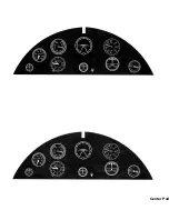
Страница 41: ...Center Pull ...

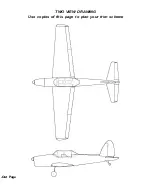
Страница 42: ...TWO VIEW DRAWING Use copies of this page to plan your trim scheme Out Page ...

Отзывы: