Dynacord A112A Скачать руководство пользователя страница 4

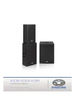
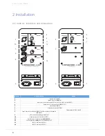
A 112A | A 115A | A 118A

4

IMPORTANT SAFETY INSTRUCTIONS

1.

Read these instructions.

2.

Keep these instructions.

3.

Heed all warnings.

4.

Follow all instructions.

5.

Do not use this apparatus near water.

6.

Clean only with a dry cloth.

7.

Do not cover any ventilation openings. Install in accordance with the manufacturer’s instructions.

8.

Do not install near heat sources such as radiators, heat registers, stoves, or other apparatus (including amplifiers) that produce heat.

9.

Do not defeat the safety purpose of the polarized or the grounding-type plug. A polarized plug has two blades with one wider than the other. A grounding type plug has two
blades and a third grounding prong. The wide blade or the third prong are provided for your safety. If the provided plug does not fit into your outlet, consult an electrician
for replacement of the obsolete outlet.

10.

Protect the power cord from being walked on or pinched particularly at plugs, convenience receptacles, and the point where they exit from the apparatus.

11.

Only use attachments/accessories specified by the manufacturer.

12.

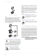
Use only with the cart, tripod, bracket, or table specified by the manufacturer, or sold with the apparatus. When a cart is used, use caution when moving
the cart/apparatus combination to avoid injury from tip-over.

13.

Unplug this apparatus during lightning storms or when unused for a long period of time.

14.

Refer all servicing to qualified service personnel. Servicing is required when the apparatus has been damaged in any way, such as power-supply cord or
plug is damaged, liquid has been spilled or orbjects have fallen into the apparatus, the apparatus has been exposed to rain or moisture, does not operate
normally, or has been dropped.

15.

Do not expose this equipment to dripping or splashing and ensure that no objects filled with liquids, such as vases, are placed on the equipment.

16.

To completely disconnect this equipment from the AC Mains, disconnect the power supply cord plug from the AC receptacle.

17.

The mains plug of the power supply cord shall remain readily operable.

18.

No naked flame sources, such as lighted candles, should be placed on the apparatus.

19.

The product should be connected to a mains socket outlet with a protective earthing connection.

IMPORTANT SERVICE INSTRUCTIONS

CAUTION: These servicing instructions are for use by qualified personnel only. To reduce the risk of electric shock, do not

perform any servicing other than that contained in the Operating Instructions unless you are qualified to do so. Refer

all servicing to qualified service personnel.

1.

Security regulations as stated in the EN 60065 (VDE 0860 / IEC 65) and the CSA E65 - 94 have to be obeyed when servicing the appliance.

2.

Use of a mains separator transformer is mandatory during maintenance while the appliance is opened, needs to be operated and is connected to the mains.

3.

Switch off the power before retrofitting any extensions, changing the mains voltage or the output voltage.

4.

The minimum distance between parts carrying mains voltage and any accessible metal piece (metal enclosure), respectively between the mains poles has to be 3 mm and
needs to be minded at all times. The minimum distance between parts carrying mains voltage and any switches or breakers that are not connected to the mains
(secondary parts) has to be 6 mm and needs to be minded at all times.

5.

Replacing special components that are marked in the circuit diagram using the security symbol (Note) is only permissible when using original parts.

6.

Altering the circuitry without prior consent or advice is not legitimate.

7.

Any work security regulations that are applicable at the locations where the appliance is being serviced have to be strictly obeyed. This applies also to any regulations
about the work place itself.

8.

All instructions concerning the handling of MOS-circuits have to be observed.

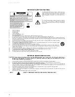
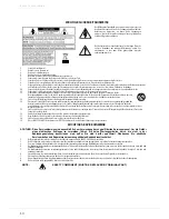
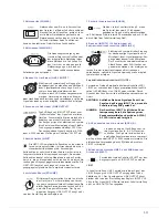
The lightning flash with arrowhead symbol, within an equilateral
triangle is intended to alert the user to the presence of uninsulated
”dangerous voltage” within the product’s enclosure that may be of
sufficent magnitude to constitute a risk of electric shock to per-
sons.

The exclamation point within an equilateral triangle is intended to
alert the user to the presence of important operating and
maintance (servicing) instructions in the literature accompanying
the appliance.

NOTE:

SAFETY COMPONENT (MUST BE REPLACED BY ORIGINAL PART)

Содержание A112A

Страница 1: ...A 112A A 115A A 118A A Line Powered Speakers Owner s Manual Bedienungsanleitung...

Страница 2: ...A 112A A 115A A 118A 2...

Страница 3: ...mplifier and Cooling 8 Quickstart 8 APPENDIX ANHANG 16 Specifications 16 Block Diagram 18 Dimensions 20 Setup Examples 21 INHALT EINF HRUNG 11 Lieferumfang Auspacken und berpr fen 11 Garantie 11 INSTA...

Страница 4: ...candles should be placed on the apparatus 19 The product should be connected to a mains socket outlet with a protective earthing connection IMPORTANT SERVICE INSTRUCTIONS CAUTION These servicing instr...

Страница 5: ...or and a XLR link output socket Setting up a small yet very powerful system turns out to be a piece of cake when combining with DYNACORD CMS mixing consoles e g CMS 600 3 They are the perfect fit and...

Страница 6: ...r forl audio signal LINK OUTPUT 5 Limit indicator LIMIT 6 Volume level control VOLUME 7 Polarity switch 0 180 PHASE 8 Input connector for audio signal INPUT 2 with sensitivity selection switch MIC LIN...

Страница 7: ...VOLUME Level control for adjusting the volume of the loudspeaker The level control affects the power amp s overall amplification VOLUME control does not affect the level of the LINK OUTPUT connector...

Страница 8: ...ce the temperature has returned to within the operating range the amplifier will turn back on This may happen when the speaker is operated in very high ambient temperatures and the enclosure is expose...

Страница 9: ...sitions i e volume settings 8 Your system is now ready for operation Individual sound adjustments necessary can be made using the controls of the mixer s corresponding input chan nels 9 Now have fun w...

Страница 10: ...oder Trinkgef e auf dem Ger t 16 Um das Ger t komplett spannungsfrei zu schalten muss der Netzstecker gezogen werden 17 Beim Einbau des Ger tes ist zu beachten dass der Netzstecker leicht zug nglich...

Страница 11: ...ein XLR Kabel auf weitere Boxen weiterge schleift werden F r das wiedergegebene Signal steht ein Lautst rke Regler ein Schalter f r die Umschaltung auf Monitor Betrieb sowie ein Schalter zur Aktivieru...

Страница 12: ...nals mit Line Pegel LINK OUTPUT 5 Anzeige Limiter LIMIT 6 Lautst rke Regler VOLUME 7 Polarit tswahlschalter 0 180 PHASE 8 Eingang XLR Klinke f r Audio Signal mit Line oder Mikrofon Pegel INPUT 2 9 Ste...

Страница 13: ...meidung von Verzer rungen in vorgeschalteten Mischpulten sollte dieser Regler normalerweise zwischen 0 dB und 6 dB eingestellt werden Der Signal pegel am Ausgang LINK OUTPUT h ngt nicht von der Einste...

Страница 14: ...ten Hochpass w hlen Sie die Schalterstellung FULLRANGE um eine Reihenschaltung von Hochpassfiltern zu ver meiden Die Schalterstellung LO CUT ist auch f r Delay An wendungen geeignet wenn kein hoher Ba...

Страница 15: ...nnen nun die A 112A mit dem beiliegenden Netzkabel an das Stromnetz anschliessen Der Stek ker wird hierzu in die Buchse MAINS IN gesteckt Mit dem Netzschalter POWER setzen Sie die A 112A in Betrieb I...

Страница 16: ...al 90 x 50 Omnidirectional Audio Input LINE 1 or MIC LINE 2 INPUT 1 XLR and 1 4 TRS combination INPUT 2 XLR and 1 4 TRS combination INPUT XLR and 1 4 TRS combination Audio Input AUX Stereo RCA unbalan...

Страница 17: ...A 112A A 115A A 118A 17 Illustration 3 1 Frequency response of A 112A Illustration 3 2 Frequency response of A 115A Illustration 3 3 Frequency response of A 118A...

Страница 18: ...PROCESSING UNIT VOLUME MONITOR 5x20mm T5A POWER MAINS 1 L MAINS POWER SUPPLY MAIN LO CUT FULLRANGE THERMAL PROTECTION LIMITER HF FIR X OVER EQ HF 220V 240V 50Hz 60Hz LEVEL LINE 1 INPUT 2 AUX L R LIMI...

Страница 19: ...agram of A 118A DIGITAL SIGNAL PROCESSING UNIT INPUT LINK OUTPUT VOLUME POLARITY FILTERS THERMAL PROTECTION PHASE 0 180 LIMITER LF LF PROTECTIONS CLASS D AMPLIFIER 5x20mm T5A POWER MAINS 1 L MAINS POW...

Страница 20: ...A 112A A 115A A 118A 20 3 3 Dimensions Abmessungen A 112A A 115A A 118...

Страница 21: ...A 118A 21 3 4 Setup Examples Systembeispiele FULL RANGE SUBWOOFER CONFIGURATION Illustration 3 6 Stacking full range systems with subwoofers Dual A 112A or A 115A with LO CUT setting selected dual A 1...

Страница 22: ...A 112A A 115A A 118A 22 DAISY CHAIN CONFIGURATION Illustration 3 7 Daisy chaining full range systems dual A 112A or A 115A...

Страница 23: ...A 112A A 115A A 118A 23 MONITOR CONFIGURATION Illustration 3 8 Using full range systems as Monitors Dual A 112A or A 115A with MONITOR setting selected...

Страница 24: ...84 0043 49 9421 706 0 Fax 49 9421 706 265 Asia Pacific only For customer orders contact Customer Service at www dynacord com 65 6571 2534 Fax 65 6571 2699 For technical assistance contact Technical Su...

Отзывы: