
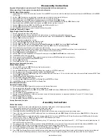

Disassembly Instructions
Important: Manufacturer’s warranty is void if tool is disassembled before warranty expires.
Disconnect tool from power source before tool repair.
Orbital Head Disassembly:
1.
Slide
61394
Switch Shaft to the random (lock) position. Use the
95823
21mm wrench to hold the orbital head in position and removed the
96188
Screw with the
95049
3/16" hex key.
2.
Hold the
18552
Housing in a vise with bronze or aluminum jaws so the orbital head assembly is facing up.
3.
Apply localized heat to the three
95235
Screws and use a 9/64" hex key to remove these.
4.
Apply localized heat to the
57069
Balancer Shaft and remove the shaft along with the
56052
Bearing.
5.
Use the
96346
2" Bearing Separator and the
96232
#2 Arbor Press to remove the
56052
Bearing from the
57069
Balancer Shaft.
6.
Apply localized heat to
61398
Locking Pin Bushing and use
96364
Slotted screwdriver to remove.
7.
Remove
61935
Switch Spring,
61393
Pin,
61397
Spring, and
61396
Locking Pin Insert.
8.
Remove
61394
Switch Shaft from Orbital Head Housing.
9.
Use the
95823
21mm Wrench to remove the orbital head from the spindle.
Orbital Head Disassembly Complete.
Right Angle Head Disassembly:
1.
Remove side handle and orbital head assembly.
2.
Secure
53600
Right Angle Housing, against both side handle bosses, in a padded vise with spindle facing upward.
3.
Using
97782
Pin Wrench (
ordered separately) or an adjustable pin wrench, remove
50963
Retainer. (
Left Hand Threads
)
4.
Remove
50899
Shaft Seal from retainer.
5.
Pull spindle and gear assembly from housing.
6.
Press spindle through
97679
Bearing and spiral bevel gear.
7.
Remove shims and
53608
Wick from right angle housing.
8.
Remove
53650
Lock Ring from right angle housing (
Left Hand Threads
) and from
53695
Gear Casing (
Right Hand Threads
).
9.
Remove angle head from vise and remove
96325
Bearing by pressing
53649
Gear Oil Plate through housing.
10.
Pull pinion gear, bearing and coupler sub-assembly from angle housing.
11.
Secure gear, bearing and coupler sub-assembly by the pinion gear wrench flats and remove the
50902
Coupling Insert (twist counterclockwise).
12.
Secure
53635
Adapter using an allen wrench and remove pinion gear (twist counterclockwise).
13.
Press
53635
Adapter through
01266
Bearing.
14.
Remove
04014
Set Screw from
53695
Gear Casing and remove gear casing (
Right Hand Thread
) from motor housing.
15.
Slide
53665
Ring Gear from gear casing.
16.
Secure planetary carrier using
53698
Wrench (
ordered separately) and remove
51969
Coupling (twist counterclockwise).
17.
Press planetary carrier thread end through
54520
Bearing.
18.
Remove
96498
Wave Spring.
19.
Press
53679
Pins from carrier to remove gears.
Right Angle Head Disassembly Complete.
Motor Disassembly:
1.
Remove
53651
Spacer and
96498
Wave Spring from housing assembly.
2.
Pull motor assembly from housing.
3.
Remove
53620
Motor Adapter with
95438
O-Ring.
Note:
Step 3 applies to 4,500 RPM models only.
4.
Remove governor assembly by using a slotted screwdriver. (
Left Hand Thread
)
5.
Secure
51925
Cylinder using
96209
Motor Repair Clamp (
ordered separately) and place a 1/8" (3 mm) drift pin to the base of the terminal thread and press
51921
Rotor
from the
02057
Rear Bearing.
6.
Slide
02057
Rear Bearing from
51923
Rear Bearing Plate.
7.
Remove
51925
Cylinder and
51926
Blades.
9.
Press rotor through
54520
Bearing,
51922
Front Bearing Plate and
51927
Rotor Spacer.
10.
Slide
54520
Bearing and shims from
51922
Front Bearing Plate.
Motor Disassembly Complete.
Housing Disassembly:
1.
Secure housing using
51989
Repair Collar (
see back cover for Optional Accessories).
2.
Remove inlet bushing with muffler assembly (twist counterclockwise).
3.
Remove
53682
Gasket,
51943
Spring,
96442
O-Ring,
51940
Spacer,
94528
Felt Silencer,
53686
Muffler Cap,
94924
Wave Spring and
53683
Spacer
from
53681
Inlet Bushing.
4.
Remove
51944
Tip Valve and
51945
Valve Seat.
5.
Remove housing and
51989
Repair Collar and lay collar on bench with flange facing down so it is supporting throttle lever. Place a 3/32" (3 mm) drift pin on
96444
Pin and tap pin thru housing.
6.
Remove
51946
Valve Stem Assembly.
7.
Remove
96443
O-Ring from
51946
Valve Stem Assembly.
Housing Disassembly Complete.
Assembly Instructions
Motor Assembly:
Important:
Be sure parts are clean and in good repair before assembling. Follow grease, oil and torque specifications.
1.
Place rotor into a padded vise with gear teeth or male thread facing upwards.
2.
Slip
51927
Rotor Spacer over rotor shaft and down against rotor body face.
3.
Press
96441
Coiled Pin into
51922
Front Bearing Plate. Make certain, coiled pin does not protrude beyond internal bearing surface.
4.
Place a .002" shim into the base of
51922
Front Bearing Plate as an initial spacing and slide
54520
Bearing to the front plate base.
Note: 51951
Shim Pack contains
001" and .002" shims.
5.
Slip bearing/bearing plate assembly onto rotor. Add one drop of Loctite
®
#243 (or equiv.) to
51921
Rotor 3/8-24 male thread and screw
51969
Coupling Nut into place
(Torque to 17 N•m 150 lb.-in.).
Note:
Step 5 applies to 4,500 RPM models only, omit step 6.
6.
Press Bearing/Bearing Plate assembly onto rotor.
7.
Check clarence between rotor and front bearing plate by using a .001" feeler gauge. Clarence should be between .001" – .0015". Adjust clarence by repeating steps 4,5
and 6 with different shims if necessary.
8.
Once proper rotor gap clarence is achieved, install well lubricated
51926
Blades (4) into rotor slots. Dynabrade recommends lubricating blades with
95842
Air Lube.
9.
Install
51925
Cylinder over rotor and front plate raised boss. Align coiled pin on front plate to cylinder slot.
10.
Press
96441
Coiled Pin into blind hole on
51923
Rear Bearing Plate. Press (2)
96445
Coiled Pins into the back side of rear bearing plate.
11.
Peel backing off
51924
Gasket and apply it firmly in place onto
51923
Rear Bearing Plate.
12.
Place
51923
Rear Bearing Plate over rotor mandrel and insert raised boss on rear bearing plate into cylinder diameter, while inserting short coiled pin into cylinder slot.
Be sure inlet slot on rear bearing plate lines up with inlet slot on cylinder. To correct alignment flip cylinder end to end and repeat step 9 for correct assembly.
(continued on next page)


