


- 2 -
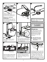
INSTALL 3/8"-16 HEADLESS
HANGER BOLTS
Mark locations for hanger bolts 5" on
either side of Center Line and 5" from
the wall. Predrill marked locations and
install hanger bolts.
INSTALL CLOSET BOLTS
Install closet bolts in flange channel
and slide into place parallel to wall.
TIP:
Place 2 pieces of masking tape
on floor (as shown) to help with
alignment in step 6.
Apply weight evenly. Do not move
after placement. Water tight seal
may break.
Connect water line to tank but DO NOT
TURN SUPPLY ON!!! Install all nuts and
washers and insure not to over tighten
to avoid damage to bowl.
To aid the connection of the flapper
chain to the Push Button Chain Arm,
carefully remove the flapper from the
overflow tube
Carefully place tank lid over top of tank
at slight angle so end of trip lever rod is
over chain/flapper area. Connect chain
to trip lever (ref illustration) and recon-
nect flapper to overflow tube, finally
moving lid to correct finished position.
NOTE:
Clearance of tank lid to tank will
be very limited once chain is connected
to chain arm and flapper.
Install Flush Button Assembly through
hole in tank lid, attach with Lock Nut.
Insure Push Button Chain Arm is in
position or direction as referenced in
illustration.
7302254-100 Rev. B (8/16)
3
6
8
4
7
9
10
5
!
WARNING:
Overtightening of water supply
line nuts could result in breakage
and potential flooding. If the
connection leaks after hand
tightening, replace the supply
line. Do not use any type of
sealant on the water supply
connection.
Use of plumber’s putty,
pipe dope, or any other
type of sealant will void
the warranty.
For seat installation,
see instructions
included with seat.
*
!
CLOSET
BOLT
PLATE COVER
WASHER
NUT
Press
firmly.
WAX RING
CLOSET FLANGE
DRAIN
CENTER LINE
3/8" (10 mm) -16 HEADLESS
HANGER BOLTS
5" (127 mm)
CLOSET BOLTS
5" (127 mm)
7" (178 mm)
BACK OF
LID TANK
FLUSH
BUTTON
ASSEMBLY
ANGLE FROM
CENTER
120
CHAIN ARM OR
TRIP LEVER ROD
10
FRONT OF TANK LID
FLUSH BUTTON
ASSEMBLY
FLUSH VALVE
CHAIN
CHAIN ARM/
TRIP LEVER ROD
FLAPPER
CONNECTION
POINT


