


- 18 -
general lubricant between the aluminum tubing sections. Oils or general lubricants can cause
poor electrical connections for radio frequencies.
3. Clean the outside of the aluminum tubing to clear any dirt or foreign material that would cause
the clamps to malfunction during assembly.
4.
JTL-12555 Jet-Lube
™
SS-30
Anti-Oxidant should be used between all antenna element
sections. Jet-Lube
™
SS-30 is an electrical joint compound to affect a substantial electrical
connection between metal parts such as
telescoping aluminum tubing
or other antenna pieces.
It ensures high conductivity at all voltage levels by displacing moisture and preventing
corrosion or oxidation.
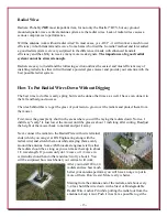
5. When assembling the aluminum tubing sections, ensure the area is clear of grass, dirt or other
foreign material that could cause problems during assembly of the closely fitted telescoping
sections.
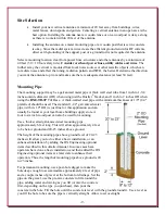
Assemble the vertical sections in an area that is flat and has sufficient room for the length of the
antenna during assembly.
Assembly is easier if the tubing sections are pre-marked. A dark color felt-tip marker works well.
Locate the hardware pack containing the element clamps.
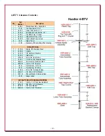
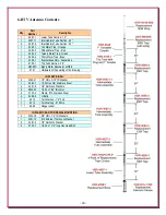
Refer to the following 4-BTV, 5-BTV or 6-BTV assembly instructions, depending on your antenna,
for element clamps, tubing and trap placement.
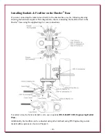
Slide all the clamps over each section before putting them together. You can lightly
tighten the clamps just below the slits in each section to hold them until needed.
Align the clamp screws on each section to face the same direction.
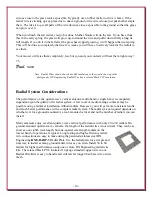
At final assembly, body of the clamp should be positioned between the slits in the
tubes and 1/8" from the edge of each tube as shown to the right.
Making sure dirt or grass does not adhere to the sections to be joined. The body of the
element clamp is positioned between the slits and tighten securely.
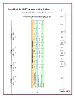
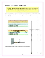
The following charts show the suggested starting measurements for the 4/5-BTV and 6-BTV
antennas. Note the charts show different measurements for various installation methods.
4-BTV and 5-BTV Approximate Starting Dimensions
Type of Installation
A1
A2
B1
B2
C1
C2
D
On a roof with 4 ft. pipe and radials
2-1/8"
2-1/8"
2"
2"
1-7/8"
1-7/8"
61-1/8"
On metal tower w/radials dropped 45º
2"
2"
2"
2"
1-1/8"
1-1/8"
61-1/8"
Ground Mounted - No Radials
0"
0"
1/2"
1/2"
1-1/16"
1-1/16"
62-1/8"
Ground Mounted with Radials
0"
2"
0"
2"
0"
1-1/2"
62-1/8"
6-BTV Approximate Starting Dimensions
Type of Installation
A1
A2
B1
B2
C1
C2
D1
D2
E
On a roof with 4 ft. pipe and
radials
2-1/8"
2-1/8"
2"
2"
1-7/8"
1-7/8"
1-1/2"
1-1/2"
1"
Ground Mounted - No Radials
0"
0"
1-1/2"
1-1/2"
1-1/16"
1-1/16"
2"
2"
2"
Ground Mounted with Radials
0"
2"
0"
2"
0"
1-1/2"
0"
2"
1-1/2"
Содержание 4-BTV
Страница 53: ...53 Hustler BTV Replacement Parts Diagram...


