Dwin HDP-500 Скачать руководство пользователя страница 8

8 of 29 


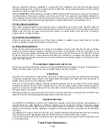
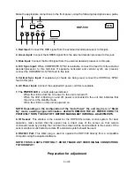
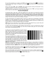
Make the appropriate connections to the front panel, using the following descriptions as a guide.
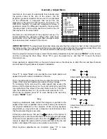
 

DWIN

HDP-500

RED     GREEN    BLUE


 H/C         V

SYNC     SYNC

RS232C
  Input

IR Input

120VAC 60Hz

7                  8              9

1         2        3        4          5                      6


1. Red Input:

 Connect the RED signal from the external decoder/processor to this jack. 

 
2. Green Input:

 Connect the GREEN signal from the external decoder/processor to this jack. 

 
3. Blue Input:

 Connect the BLUE signal from the external decoder/processor to this jack. 

 
4. H/C Sync Input:

 When COMPOSITE SYNC is available, connect the feed from the external 

decoder/processor to this terminal. If separate horizontal and vertical synch are present, 
connect the HORIZONTAL SYNC feed to this jack. 

 
5. Vertical Sync Input:

 If separate sync feeds are being used, connect the VERTICAL SYNC 

feed to this jack. 

 
6. AC Power Input:

 Connect the supplied AC power cord this receptacle. 

 
7. The POWER LED

 is a multi-purpose indicator:  


When the LED is dark the AC power to the unit is turned off. 
When the LED is flashing on and off, power is connected to the unit, this indicates that 
the unit is in the standby mode. 


When the LED is on the unit is powered on.  


NOTE: Depending on the configuration of the “Auto Power” the unit may be in a “Stand 
By” mode, awaiting signal information. ALWAYS REMOVE THE AC POWER CORD TO 
POSITIVELY TURN THE UNIT OFF BEFORE MAKING ANY INTERNAL ADJUSTMENTS.


8. IR Sensor:

 This window is the sensor for the HDP-500’s remote control system. For best 

operation, make certain that the sensor has a direct view of the screen so that remote 
commands made by pointing the control at the screen will be bounced back to the sensor. If the 
sensor window is obstructed a remote IR extension system should be used. 

 
9. RS232C Port:

 This DB-9 plug is used to operate the HDP-500 directly from a compatible 

computer using the supplied software.  
 

NOTE: THIS IS A DATA PORT ONLY. DO NOT MAKE ANY VIDEO SIGNAL CONNECTIONS 
TO THIS INPUT! 


Preparation for adjustment


Содержание HDP-500

Страница 1: ...UPERDATA PROJECTION MONITOR Installation and Operating Instructions Read these instructions completely before operating this unit Contents subject to change without notice or obligation Printed in USA...

Страница 2: ...ents ________________21 Blanking Adjustments __________22 Size Adjustments ________________22 Source Memory Entry __________22 Global Setup Adjustments __________23 Power On Control ________________23...

Страница 3: ...ur home consult your appliance dealer or local power company 9 This unit is equipped with a three conductor polarized alternating current line plug This plug will fit into the power outlet only one wa...

Страница 4: ...erating the projector IMPORTANT INFORMATION FOR THE USER Note This equipment has been tested and found to comply with the limits for a Class B digital device pursuant to Part 15 of the FCC Rules The l...

Страница 5: ...hm positive BNC H V Sync 0 7 4 0 V p p 75 ohm positive or negative BNC Convergence System Digital system with 60 preset memory positions Static and dynamic wave convergence via wireless remote or RS 2...

Страница 6: ...screen distance is correct for the size and aspect ratio of the screen Adjust the unit while it is easily accessible BEFORE mounting it to a ceiling or placing it in the final installation Pre setting...

Страница 7: ...it should be provided Avoid the use of circuits connected to mechanical equipment as they may induce noise in the video system Pre Installation Adjustment and Set Up We strongly recommend that these i...

Страница 8: ...POWER LED is a multi purpose indicator When the LED is dark the AC power to the unit is turned off When the LED is flashing on and off power is connected to the unit this indicates that the unit is i...

Страница 9: ...certain adjustments it is necessary to remove the unit s cover First loosen the screws at either side of the green center lens about 1 2 until the cover panel pops up It is not necessary to completely...

Страница 10: ...at any time Pressing the MENU button while a sub menu is displayed on the screen will return back to the Main Menu Pressing the MENU button while the Main Menu is displayed will cancel the menus 4 Pr...

Страница 11: ...appear on the screen Main Menu 1 Brightness 2 Contrast 3 Center Convergence 4 Centering 5 Blanking 6 Size 7 Source LD 5 31 468KHz 60 00Hz 8 Adjust 9 Set Up HDP 500 16 FF If the menu is not in clear fo...

Страница 12: ...by loosening the wing nut at the rear of the green center lens so that it is loose but do not remove it Rotate the lens barrel by holding the lens with one hand and moving the nut post with the other...

Страница 13: ...l phases of projector installation Size Press 1 to select Size and note that the cross hatch pattern will appear along with numeric indications of the size For a conventional 4 3 aspect ratio screen a...

Страница 14: ...he remote until the outer edges of the picture are square to the corners with no apparent bowing of the lines at the top bottom or sides When Edge Pin adjustments are complete press 5 to move directly...

Страница 15: ...to the screen At the menu screen use the and buttons on the remote until the outer edges of the picture at the left right sides and top bottom are parallel to each other insert graphic here The lines...

Страница 16: ...e tilt of the red channel so that it matches the green channel Use the buttons until the red line that runs directly though the vertical center of the screen covers the underlying green line 4 Red Key...

Страница 17: ...trols those adjustments are designed to present the best possible picture for viewing During some set up procedures however it may be desirable to change the signal level only for the purpose of the a...

Страница 18: ...procedure by pressing 1 from the main Convergence menu The first thing to appear will be a WARNING message reminding you entering the Coarse Adjustment menu will erase any fine adjustments settings a...

Страница 19: ...nt is complete press ENTER to return to cursor movement and use the directional arrow keys to move to the next adjustment point Continue the process until each adjustment point has been converged When...

Страница 20: ...at the Master Gray Scale menu If you are not at that screen first call up the main menu by pressing the MENU key on the remote At the Main Menu press 8 to reach the Adjust menu and then 2 to reach th...

Страница 21: ...he upper right corner of the screen Use the and buttons on the remote to adjust the setting so that it is acceptable Center Convergence Since the master point convergence has been established during t...

Страница 22: ...When finished press 4 to move to the Right Blanking adjustment At the Blanking Right screen use the and directional arrow keys to place the outer edge of the active picture area at the right side of...

Страница 23: ...king areas A total of 60 separate memories may be entered to the system when all inputs are combined When memory settings are entered they are automatically routed to the memory group for the proper s...

Страница 24: ...ember that passwords for this system are case sensitive Any password created using upper and lower case letters must be repeated EXACTLY as it was originally entered in order to unlock the system NOTE...

Страница 25: ...to the next position and set the next character using the and arrow buttons Again when set use the button to move to the next spot and the and arrow buttons to select the character When the complete...

Страница 26: ...er side of the center lens Table 1 Horizontal Vertical Connector Settings H2 Lead 1 H2 Lead 2 V2 Lead 1 V2 Lead 2 Convergence Jumper Front Floor Blue Red Blue Red FF Front Ceiling Red Blue Red Blue FC...

Страница 27: ...120 diagonal screen this would result in a screen to mounting bracket distance of 138 Remove the projector top panel cover First loosen the screws at either side of the green center lens about 1 2 unt...

Страница 28: ...ew closest to the red or blue tube DO NOT loosen the screws that secure the green tube LOOSEN THE SCREWS ONLY DO NOT remove them When the screws have been loosened use two hands to gently move the red...

Страница 29: ...adjustment damage caused by accident unreasonable use or neglect damage from failure to follow instructions contained in your operating instructions damage from the performance of repairs by someone n...

Страница 30: ...the warranty Please save the original shipping cartons A charge will be made for additional cartons If your product needs service you should notify us at DWIN Electronics Inc 710 N Mariposa St Burban...

Отзывы: