I-1
2
1
3
4
5
I
A
I
Index
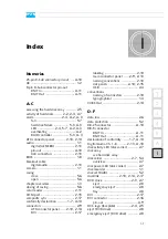
Numerics
25-pin D-Sub connector pin-out
................................................ 1-2
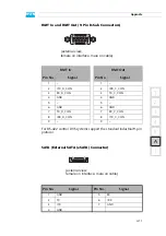
9-pin D-Sub connector pin-out
RMT In
..................................A-11
RMT Out
...............................A-11
A-C
accessing the hard disk array
activity of hard disks
alarm
.............................2-4, A-2, A-3
fan
.......................................... 5-7
hard disk failure
LED
.................. 2-4, 5-7, A-2, A-3
.............................A-2
RAID controller
ATX connector panel
audio
............................................ 1-1
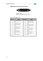
pin-out
..................................A-10
XLR connectors
BIOS
............................................. 1-8
breakout cable
digital audio
........................... 2-13
camera
.......................................... 1-1
casing
close
....................................... 5-6
open
....................................... 5-6
chapter overview
............................ 1-3
closing of casing
............................. 5-6
................................. 2-11
COM port
................................... 2-15
............................ 2-17
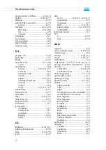
connectors
.................................... 2-9
ATX connector panel
DVI
....................................... 2-17
.................................. 2-10
main connector panel
naming conventions
slot panels
.....................2-10, 2-15
USB
......................................... 2-4
conventions
naming of connectors
typographical
........................... 1-4
CVBS Out
.................................... 2-14
D-F
data loss
........................................ 2-6
data protection
............................... 5-2
DB-25 connector
..........................A-10
DB-9 connector
RMT In
..................................A-11
...............................A-11
declaration of conformity
Digital Audio Ch. 1-8
disk activity LED (disk carrier)
disk array
disk carrier
..............................2-7, 5-4
overview
.................................. 2-7
disk power LED (disk carrier)
.................................. 1-1
disk set (RAID)
............................... 5-2
................... 2-10, 2-14, 2-17
DVD drive
..............................2-3, 2-7
eject
........................................ 2-8
emergency eject
tray
......................................... 2-8
DVI
............................................. 2-17
.............................. 2-16
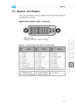
pin-out
....................................A-9
eject (DVD drive)
............................ 2-8
emergency eject (DVD drive)
Содержание Pronto3
Страница 1: ...Pronto3 Hardware Guide Version 1 0 Digital Disk Recorder Pronto3 Hardware Guide ...
Страница 2: ......
Страница 6: ......
Страница 8: ......
Страница 36: ...2 18 Pronto3 Hardware Guide ...
Страница 38: ...3 2 Pronto3 Hardware Guide ...
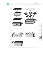
Страница 65: ...A 13 2 1 3 4 5 Appendix I A Figure 3 Figure 4 Figure 5 a b c Box A Box B Box B Box B Box B Box B ...
Страница 68: ...A 16 Pronto3 Hardware Guide ...
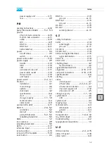
Страница 72: ...I 4 Pronto3 Hardware Guide VTR 1 1 warranty 1 7 XLR connectors audio 2 13 ...

