2-11
Overview
2
1
3
4
5
I
A
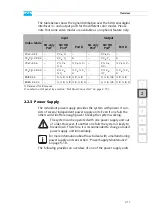
The table below shows the signal distribution over the SDI (serial digital
interface) in- and output ports for the different color modes. Please
note that some video modes are available as an optional feature only:
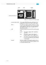
2.2.3 Power Supply
The redundant power supply provides the system with power. It con-
sists of several independent power supply units: Even if one fails the
others will still offer enough power to keep the system working.
The following provides an overview of one of the power supply units:
Video Mode
Input
Output
SD-only
Port
1
1) Reserved for future use.
SD/HD
Port
2
2) Located on slot panel (see section “Slot Panel Connectors” on page 2-15).
Port B
SD-only
SD/HD
Port B
YC
b
C
r
4:2:2
–
Y, C
b
, C
r
–
–
Y, C
b
, C
r
–
YC
b
C
r
A 4:2:2:4 –
Y, C
b
, C
r
A
–
Y, C
b
, C
r
A
YC
b
C
r
4:4:4
–
Y, ½ C
b
,
½ C
r
½ C
b
, ½ C
r
–
Y, ½ C
b
,
½ C
r
½ C
b
, ½ C
r
YC
b
C
r
A 4:4:4:4 –
Y, ½ C
b
,
½ C
r
½ C
b
, ½ C
r
,
A
–
Y, ½ C
b
,
½ C
r
½ C
b
, ½ C
r
,
A
RGB 4:4:4
–
G, ½ R, ½ B ½ R, ½ B
–
G, ½ R, ½ B ½ R, ½ B
RGBA 4:4:4:4
–
G, ½ R, ½ B ½ R, ½ B, A –
G, ½ R, ½ B ½ R, ½ B, A
The system can be operated with one power supply unit out
of order. However, if another one fails the system is likely to
break down. Therefore, it is recommended to change a failed
power supply unit immediately.
For more information about how to deal with a malfunctioning
power supply unit see section “Power Supply Maintenance”
on page 5-10.
Содержание Pronto3
Страница 1: ...Pronto3 Hardware Guide Version 1 0 Digital Disk Recorder Pronto3 Hardware Guide ...
Страница 2: ......
Страница 6: ......
Страница 8: ......
Страница 36: ...2 18 Pronto3 Hardware Guide ...
Страница 38: ...3 2 Pronto3 Hardware Guide ...
Страница 65: ...A 13 2 1 3 4 5 Appendix I A Figure 3 Figure 4 Figure 5 a b c Box A Box B Box B Box B Box B Box B ...
Страница 68: ...A 16 Pronto3 Hardware Guide ...
Страница 72: ...I 4 Pronto3 Hardware Guide VTR 1 1 warranty 1 7 XLR connectors audio 2 13 ...


