background image

6

Electrical installation

6.1

Electrical connection without
a mains plug

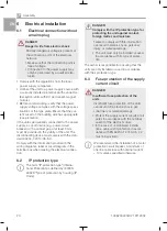
DANGER
Danger to life from electric shock

Mortally dangerous voltage is present at
the connection point of the electrical
network.

Make sure that the connection point is
free of voltage.

Connection to the power supply may
only be performed by a qualified elec-
trician.

Comply with the regulations from the local
power supply companies.

Connect the unit to a power supply source with
a correctly installed protective earth conductor.
(Exception: units with DC permanent-magnet
motors.)

Before commissioning, verify that the power
supply voltage complies with the voltage speci-
fications of the type plate. Ensure that the cur-
rent circuit on the building side has appropriate
fuse protection.

If the unit is permanently connected to the power
supply, a cut-off device (e.g. power circuit
breaker) with a contact gap of at least 3 mm
must be provided in the vicinity of the unit. The
disconnecting device must comply with the stan-
dard 60204-1:2010-05, 5.3.
Comply with the information provided in the
wiring diagrams, label or circuit diagram in the
terminal box when making the electrical connec-
tion.

6.2

IP protection type

The term "IP protection type" (Interna-
tional Protection) is defined by IEC/EN
60529 "Type of protection by housing (IP
Code).

DANGER
Comply with the IP protection type for
protecting the unit against contact,
foreign matter, and moisture

Failure to comply with this information
can result in electric shock, personal
injury, or material damage.

The unit must only be installed or used
in accordance with its type of protec-
tion.

The owner is responsible for ensuring that the
units are only installed or used in accordance
with their protection type.

6.3

Fuse protection of the supply
current circuit

DANGER
Insufficient fuse protection of the
units

Insufficient fuse protection of the units
can result in fire, electric shock, per-
sonal injury or material damage.

Protect the supply current circuits at all
poles in accordance with the nominal
current of the electric motors.

In the case of unmonitored installa-
tions, overcurrent protection in accor-
dance with EN 60204-1:2010-05, 7.2
must be provided.

We recommend the installation of a motor
protection circuit breaker. A minimum of
one line cable fuse with nominal current
+ 10% unless specified otherwise.

Assembly

20

1035200220L02 1911V002

EN

Содержание Marathon 1035200100

Страница 1: ...EN Marathon 1 and 2 cylinder oil free compressor Installation and operating instructions 1035200220L02 1035200220L02 1911V002...

Страница 2: ......

Страница 3: ...Requirements 19 5 1 Setup 19 5 2 Vibration dampening 19 5 3 Installation position and fasten ing 19 5 4 Noise reduction 19 6 Electrical installation 20 6 1 Electrical connection without a mains plug...

Страница 4: ...e warnings are structured as follows SIGNAL WORD Description of the type and source of danger Here you will find the possible conse quences of ignoring the warning Follow these measures to avoid the d...

Страница 5: ...site of operation for the operation of this unit Check the function and condition of the unit prior to every use Do not convert or modify the unit Comply with the specifications of the Installa tion a...

Страница 6: ...dust free rooms protected from contaminants If possible retain the packaging material Ambient conditions during storage and trans port Ambient conditions during storage and transport Temperature C 25...

Страница 7: ...xx The vibration damper set is not included in the scope of delivery and must be ordered separately Vibration damper set 1035100410 Marathon 1035200100 Product name Article number Compressor unit 1035...

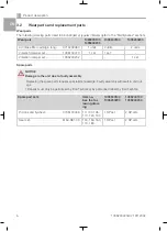
Страница 8: ...5200202 1 set Spare parts NOTICE Damage to the unit due to faulty assembly Replacing the spare parts requires specialist knowledge Faulty assembly will result in unit out age Repairs must only be perf...

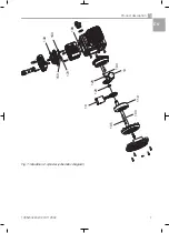
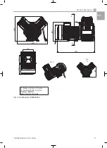
Страница 9: ...110 100 10 120 120 130 10 180 140 160 170 150 105 Fig 1 Marathon 2 cylinder schematic diagram Product description 1035200220L02 1911V002 7 EN...

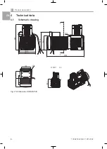
Страница 10: ...4 Technical data 4 1 Schematic drawing 180 3 289 194 8 425 3 201 9 156 4 G1 4 A A 153 7 SCHNITT A A 116 3 100 125 1 0 2 Fig 2 Dimensions 1035300100 Product description 8 1035200220L02 1911V002 EN...

Страница 11: ...ision nur f r Form Fit Function VZ revision only for form fit function nderungen vorbehalten Subject to change without notice M1 5 10 3 125 100 124 6 173 5 A A 1 5 Fig 3 Dimensions 1035300200 Product...

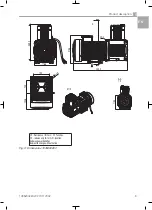
Страница 12: ...350 4 278 425 3 22 8 201 2 156 4 G1 4 A A 183 7 SCHNITT A A 116 3 100 125 10 2 Fig 4 Dimensions 1035200100 Product description 10 1035200220L02 1911V002 EN...

Страница 13: ...revision only for form fit function nderungen vorbehalten Subject to change without notice 350 2 284 4 433 5 175 215 5 12 5 G1 4 A A M 1 5 124 3 100 125 204 A A 1 5 Fig 5 Dimensions 1035200200 Product...

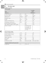
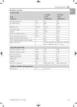
Страница 14: ...tection switch motor No No VFD variable frequency drive capable Yes Yes Mains connection Total length 890 mm length from terminal box con nection approx 770 mm General technical data Delivery quantity...

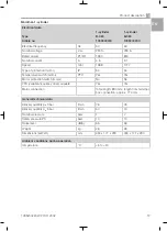
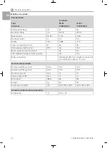
Страница 15: ...or protection switch motor No No VFD variable frequency drive capable Yes Yes Mains connection Total length 890 mm length from terminal box connection approx 770 mm General technical data Delivery qua...

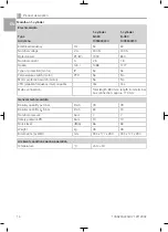
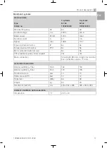
Страница 16: ...r protection switch motor No No VFD variable frequency drive capable Yes Yes Mains connection Total length 890 mm length from terminal box connection approx 770 mm General technical data Delivery quan...

Страница 17: ...protection switch motor No No VFD variable frequency drive capable Yes Yes Mains connection Total length 890 mm length from terminal box connection approx 770 mm General technical data Delivery quanti...

Страница 18: ...ction switch motor No No VFD variable frequency drive capable Yes Yes Mains connection Total length 890 mm length from terminal box connection approx 770 mm General technical data Delivery quantity pe...

Страница 19: ...rotection switch motor No No VFD variable frequency drive capable Yes Yes Mains connection Total length 890 mm length from terminal box connection approx 770 mm General technical data Delivery quantit...

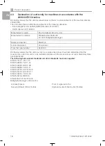
Страница 20: ...ssor From the serial number H400000 We hereby declare that the unit may only be commissioned once it has been established that the machine into which this unit is to be installed complies with the pro...

Страница 21: ...it Air must be able to flow in and out unobstructed Ventilation openings must be suffi ciently large Installed units may require an indepen dent ventilation system in unfavourable cases 5 2 Vibration...

Страница 22: ...or circuit diagram in the terminal box when making the electrical connec tion 6 2 IP protection type The term IP protection type Interna tional Protection is defined by IEC EN 60529 Type of protectio...

Страница 23: ...e current delta connection Images are shown schematically W 1 V 2 W 2 U1 U2 V 1 W2 U2 V2 U1 V1 W1 L1 L2 L3 PE Fig 8 Three phase current delta connection 6 5 Motor protection tempera ture 3 phase motor...

Страница 24: ...ir outlet are located on the cylinder head The atmospheric air is drawn in via the air intake filter on the air inlet side On the air outlet side the compressed air flows through the air line to the c...

Страница 25: ...ential danger e g pull the mains plug and prevent it from being switched back on again Maintenance interval Maintenance work Monthly Clean the surface of the unit with a non fuzzing cloth Keep the ven...

Страница 26: ...ake filter Remove the air intake filter Insert a new air intake filter 8 3 Replace the vibration dampers Observe the maintenance and repair instructions in the respective spare parts set Assembly 24 1...

Страница 27: ...ssible switch on unit again Undervoltage or overvoltage Inform an electrician Measure power supply voltage Motor defective Replace the unit Air intake filter blocked Insert a new air intake filter Red...

Страница 28: ...ys pack the units in a plastic bag Use recyclable packing material 10 2 To order spare parts Tel 49 0 71 42 9022 0 Fax 49 0 71 42 9022 99 E mail office duerr technik de The following information is re...

Страница 29: ......

Страница 30: ......

Страница 31: ......

Страница 32: ...D rr Technik GmbH Co KG Pleidelsheimer Strasse 30 74321 Bietigheim Bissingen Germany Fon 49 7142 9022 0 www duerr technik eu office duerr technik de...

Отзывы: