background image

3

IMPORTANT INFORMATION
1. NOTE

1.1 CE-Marking

All products bear the CE Conformity Marking.

This marking denotes that the products

conform to the safety guidelines and directives

laid down by the European Union.

1.2 Guidelines and Directives

The products comply with the following

guidelines and directives:
• Machinery Directive 98/37EC

including amendments.

• Electromagnetic Compatibility 89/336/EEC

including amendments.

• Low-Voltage Directive 73/23/EEC,

including amendments.

• Pressure Vessel Regulation 87/404/EEC.

1.3 General Information

• The Instructions for Assembly and Use form

an integral part of the machine. They must

be kept close to the machine and in

readiness whenever required. Precise

observance of these instructions is a prior

condition for use of the machine for the

intended purpose and for its correct

operation.

These Instructions for assembly and use

should be passed on to future users if

necessary.

• Safety for the operator as well as trouble-

free operation of the machine are only

ensured if use is made of original equipment

parts. Moreover, use may only be made of

those accessories that are specified in the

technical documentation or that have been

expressly approved and released by Dürr

Dental for the intended purpose.

If and where use is made of accessories or

consumer supplies from outside sources,

Dürr Dental are unable to assume any

guarantee for safe operation or safe

functioning.

• No warranty claims are accepted in respect

of damage arising from the use of

accessories or consumer supplies from

outside sources.

• Dürr Dental only regard themselves as being

responsible for the unit from the angle of

safety, reliability and proper functioning if

assembly, resettings, changes or

modifications, extensions and repairs have

been carried out by Dürr Dental or an

agency authorised by Dürr Dental and if the

machine is used in conformity with the

Instructions for Assembly and Use.

• The Instructions for Assembly and Use

conform to the relevant version of the

machine and the underlying safety standards

valid at the time of going to press. All

proprietary rights are reserved in respect of

the specified circuitry, methods, names,

software programs and equipment.

• Any reprinting of the technical documentation,

in whole or in part, is subject to prior written

approval of Dürr Dental.

1.4 General Information  Concerning

Safety

The compressor has been designed and

constructed by Dürr Dental in such a way that

hazards occurring when using the machine for

the intended purpose are ruled out to the

fullest extent possible. Even so, we feel

obliged to draw attention to the safety

precautions described below as a means of

ruling out any remaining hazards.

• When operating the compressor the laws

and regulations in force in the place of use

must be observed! In the interest of safe

operation, the operator and user are

responsible for observing such regulations.

• The original packaging has to be kept in a

safe place in case of having to return the

unit.

Ensure that the packaging is kept out of the

reach of children. Only the original packaging

warrants optimum protection of the unit

during transport.

In the event of the unit having to be returned

during the period of guarantee Dürr Dental

does not assume any liability for damage in

transit due to faulty or improper packing!

• Each time prior to using the machine the

user must check to ensure that it is

functionally safe and in proper condition.

• The user must be familiar with how to

operate the machine.

• The product is not intended for use in areas

Содержание 4151-51b

Страница 1: ...INSTALLATION AND OPERATION INSTRUCTIONS DÜRR COMPRESSORS Tornado Primo Duo Trio Quattro Duo Tandem Quattro Tandem Duo Tornado 2003 06 ...

Страница 2: ...n initial service 10 8 1 Environmental Conditions 10 8 2 Compressed air Connection 11 8 3 Electrical Connection 11 8 4 Placing in Initial Service 12 8 5 Setting the Motor Protection Switch 12 8 6 Checking the Safety Valve 12 8 7 Checking and Adjusting the Pressure Switch 13 8 8 Draining off Condensation Water 13 9 Circuit Diagrams 14 9 1 Version 1 N PE AC230 V 14 9 2 Version 3 N PE AC 400 V 14 9 3...

Страница 3: ...r functioning if assembly resettings changes or modifications extensions and repairs have been carried out by Dürr Dental or an agency authorised by Dürr Dental and if the machine is used in conformity with the Instructions for Assembly and Use The Instructions for Assembly and Use conform to the relevant version of the machine and the underlying safety standards valid at the time of going to pres...

Страница 4: ...mains immediately disconnect plug from mains When carrying out repair or maintenance work of any kind the mains plug must always be disconnected from the socket In addition air must be removed from all pressure lines and the pressure tank depressurised All installation work must be carried out by a suitably qualified engineer 1 6 Warning Information and Symbols In the Instructions for Assembly and...

Страница 5: ...facilities it must be ensured that the avail able medium complies with the requirements stipulated for the relevant purpose in each individual case Observe the particulars given in Chapter 4 Technical Data When installing classification and conformity rating must be carried out by the manufacturer of the ultimate product Any other use or use beyond what is specified is deemed to be not for the int...

Страница 6: ...5 7 5 5 5 7 5 Safety Valve Admissible Operating Pressure bar 10 10 10 10 10 Volume of Pressure Tank l 20 20 20 50 50 Duty cycle w DASb 50 50 50 50 50 w o DASa 100 100 100 _ _ Grade of Filtration Cartridge for compressor µm 10 10 10 10 10 Grade of Filtr Fine mesh Filter for DAS µm 1 1 1 1 1 Grade of Filtr Sterilised Filter for DAS µm 0 01 0 01 0 01 0 01 0 01 Weight w DASb kg 56 57 57 90 w o DASa 47...

Страница 7: ... 5 5 5 7 5 10 10 10 10 10 10 10 50 50 90 90 20 20 20 50 50 50 50 50 50 50 100 100 100 10 10 10 10 10 10 10 1 1 1 1 1 1 1 0 01 0 01 0 01 0 01 0 01 0 01 0 01 87 97 114 175 52 67 67 71 44 59 59 86 x 76 x 51 86 x 76 x 51 86 x 103 x63 86 x 103 x 63 64 x 49 x 46 64 x 49 x 46 64 x 49 x 46 75 x 103 x 63 64 x 49 x 44 64 x 49 x 44 64 x 49 x 44 171c 147c 86c 76c 165c 135c 76c 66c 130c 115c 65 55 100c 85c 45 ...

Страница 8: ...8 5 OVERVIEW OF FUNCTIONS OF COMPRESSORS 5 1 Compressor with Dry air System 5 2 Compressor without Dry air System 13 11 17 15b 8 10b 1 2 4 2 3 1 10a 9 11 7 6 15a 14 16 5 12 13 8 ...

Страница 9: ...ing air to flow out of the pressure tank in the opposite direction This can be heard blowing out underneath the dry air system 2 In this phase the system under goes a process of regeneration for which purpose the compressor must be at a standstill This process of regeneration will continue to repeat itself until the relative humidity originally set on the hygrostat 16 is attained Valve Unit with P...

Страница 10: ...e first time all transport security devices must be removed 8 1 Environmental Conditions The unit may only be installed and operated in dry rooms that are well ventilated and free of dust The compressor must be installed in such a way that ease of access is warranted for operation and maintenance as well as for the rating plate The unit must be mounted on a level floor base revealing adequate stab...

Страница 11: ... of the compressor is supplied fitted with a CEE connector and the 230 V version with an earthing contact type plug The regulations of local power supply companies must definitely be observed The mains voltage and frequency must conform to the data specified on the rating plate No connecting cable must be allowed to run across the unit The hot surfaces of the compressor might otherwise cause damag...

Страница 12: ...actory to certain values These values are equal to the recommended values given in Chapter 4 Technical Data for a frequency of 50 Hz The factory settings need to be checked during installation They should only be changed if necessary When changing the settings the maximum values given in Chapter 4 Technical Data must not be exceeded For checking or resetting the motor protection switch please proc...

Страница 13: ...imum pressure 10 bar on safety valve The switch off pressure must be at least 0 5 bar below the value of the safety valve as otherwise the safety valve would open and the compressor set would then fail to attain the switch off pressure thus continuing to run all the time The pressure difference p between switch on and switch off pressure can be modified This is done by turning the adjusting screw ...

Страница 14: ...230 V List of Equipment Q1 Pressure switch motor protection switch X1 Mains connection 1 N PE AC 230 V M1 Compressor motor M2 Proposed fan connection can be allocated if required 9 2 Version 3 N PE AC 400 V List of Equipment Q1 Pressure switch motor protection switch X1 Mains connection 3 N PE AC 400 V 10 11 ...

Страница 15: ...Connection to A1 X3 X4 Connection A1 to M M1 M2 Compressor motors 1 and 2 A1 Control 9 4 Version 3 N PE AC 400V 2 Aggregates Quattro Tandem List of equipment A1 Control K1 Time lag relais 13 L1L2L3 N PE 6 4 2 1 3 5 P 4 4 4 5 5 5 5 5 5 4 4 4 PE PE 2 4 6 13 21 1 3 5 14 22 4 6 3A A2 2 4 6 5 3 1 A1 2 4 6 13 21 1 3 5 14 22 4 6 3A 3 2 1 PE 6 4 U V W PE M 3 U V W PE M 3 3 2 1 PE 6 4 X1 M1 M2 X3 X4 K1 Q3 ...

Страница 16: ...rating pressure of 7 5 bar is attained once more 10 1 Switching on the Compressor Switch on the compressor at the pressure switch 11 by turning the switch 25 to position I AUTO This starts up the compressor set and the pressure tank is filled As soon as the switch off pressure is attained the compressor set will switch itself off automatically The maximum permissible operating pressure must not be...

Страница 17: ...uitably qualified engineer or our customer service staff Only use spare parts licensed by the manufacturer as well as accessories destined for the purpose Prior to performing any maintenance or repair work be absolutely sure to switch off the compressor first and disconnect from mains pull out mains plug To ensure proper functioning of the com pressor be sure to regularly carry out main tenance as...

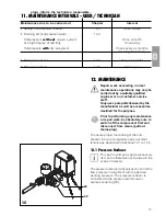
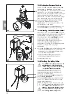
Страница 18: ...er at least once a month In countries having a high degree of atmospheric humidity the condensation water needs to be drained off every day Procedure With the compressor in the switched on state and maximum tank pressure proceed to screw open the condensation water drain cock 9 as far as possible Wait until the condensation water has completely drained off from the tank Close drain cock 9 12 4 Che...

Страница 19: ...s for filter cartridges Compressor types 5170 5171 5270 5271 Suction filter 13a 5430 982 00 Compressor types 4151 4251 4641 4681 5150 5151 5250 5251 5351 5451 Suction filter 13b 0832 982 00 Compressors with dry air system types 4151 4251 4641 4681 5151 5171 5251 5271 5351 5451 Fine mesh filter 1 1610 121 00 or Sterilisation filter 1 1640 981 00 When replacing filters the supplied sticker and docum...

Страница 20: ...oximately 10 minutes with the condensation water drain cock 9 in the open state Then switch off the unit on the pressure switch 25 close the condensation water drain cock and disconnect the mains plug 22 25 9 DISPOSAL 14 DISPOSAL OF THE MACHINE Disconnect mains plug Let off air pressure in compressed air tank by opening the condensation water drain cock 9 Dispose of the compressor in accordance wi...

Страница 21: ...is in regeneration phase humidity being reduced in tank Detect leak and seal Notify technician Air escaping downwards via the dry air system regeneration phase Leakage in compressed air line system Notify technician 4 Sound of knock ing or loud noises coming from compressor Bearing damage Suction filter contaminated Replace suction filter once a year at least Never clean the suction filter 5 Decli...

Страница 22: ...ssure switch If the pressure switch remains switched on for a brief duration and does not switch the motor off until afterwards the current consumption on the 3 phase current needs to be checked in all three phases or in one phase on AC current Measure voltage notifying the electrician if necessary For a detailed description refer to Section 8 5 Setting the Motor Protection Switch Measure current ...

Страница 23: ... aggregate pneumatically Remove pressure hose 54 T connector 53 and connector 52 Connect functioning aggregate and dry air system by directly joining pressure hose 51 and the elbow 50 fitted to this aggregate Substitute for defective aggregate Unplug the unit from the mains Turn rotary switch of the pressure switch to position 0 OFF Depressurize tank via condensa tion water drain cock Afterwards c...

Страница 24: ...time without air being withdrawn for any consumer 4 Sound of knocking or loud noises coming from compressor 5 Decline in feed performance compressor runs longer to charge tank For charging times refer to Chapter 4 Technical Data Removal of Fault Dismantle cylinder head and install new lamellar valve Replace air relief valve Check control head on dry air system Bring pressure to act upon lines Seal...

Страница 25: ...urring the control unit 64 can be dismantled on the dry air system Dismantle dry air system on compressor Remove three hexagon socket screws 65 from base of dry air system Remove control unit 64 Remove O rings 62 from base of water collecting chamber and replace by new ones Remove valve together with sealing washer and compression spring 61 and substitute by supplied parts 6 Water is dripping out ...

Страница 26: ...m the pressure tank Refer to Section 12 3 Draining off Condensation Water Wait until no further water is blown out of the drain cock Close drain cock again Bridging over the dry air system Disconnect compressor from mains so as to prevent it from starting up while rebuilding operations are in progress For this Unplug the unit from the mains Drain compressed air from pressure tank open drain cock 9...

Страница 27: ... Remove screw plug 75 along with filter 76 turn 180 and insert Tighten screw plug 75 This action serves to seal off the duct to the dry air system and the control head on the dry air is vented during stoppage through a small borehole drilled into the plug screw 75 Fault Possible Cause Removal of Fault ...

Отзывы: