background image


11   


4.3.4.


Mounting   the   water   cover   

1)


Take   the   water   cover   with   the   gasket   and   the   
mounting   materials   out   of   the   wooden   case   (see   
the   lifting   instructions   of   section   3.2).   

2)


Inspect   the   water   cover   before   installation,   

especially   the   coating.   Touch   up   when   necessary.      

3)


Clean   the   gasket   faces   and   make   sure   they   are   
free   of   defects   (burrs,   pits,   dents,   etc.).   

4)


Position   the   supplied   gasket   between   the   water   
cover   and   the   tube   bundle   (item   2   of   fig.   7).   Make   
sure   the   partitioning   corresponds   with   the   
drawing   and   the   water   cover.   
Make   sure   the   gasket   is   clean.   

Do   not   use   glue,   sealant,   grease   or   any   other   
sealing   agent   when   installing   the   SBR   gasket.


5)


Carefully   put   the   water   cover   in   place.   Check   the   
orientation,   refer   to   the   supplied   drawing.   

Mind   the   weight.   Take   care   not   to   damage   the   
coatings,   the   gasket   or   the   gasket   faces.


6)


Position   the   supplied   bolts   and   the   nuts   for   the   
collar   bolts   in   the   bolt   holes   and   fasten   hand   tight   
(see   fig.   8a   and   8b).   

7)


Tighten   all   bolts   and   nuts   alternate   and   crosswise   
with   a   torque   wrench   to   guarantee   an   even   
setting   of   the   gaskets.   

Refer   to   section   4.4.4   for   tightening   torques.   

The   water   cover   can   be   painted   on   the   outside.   

Do   not   paint   the   inside   of   the   water   box.

   The   paint   may   

be   stripped   off   by   the   fluid   and   blind   the   tubes.   


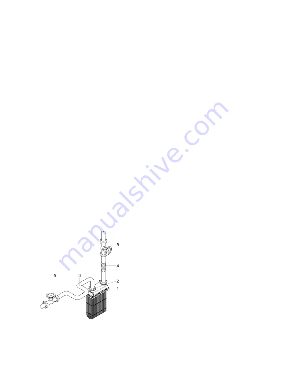
Figure   11.   Typical   piping   installation   with   an   expansion   

loop   (3),   an   expansion   joint   (4)   and   service   valves   (5),   

connected   to   the   box   cooler   flanges   (1   and   2).   

4.4.


FIXING   THE   PROCESS   PIPING   

Ensure   that   all   piping   will   be   fixed   to   the   box   cooler   
without   transferring   load   and   (piping)   vibrations   to   
the   box   cooler.   
Install   safety   devices   to   prevent   overpressure   and   
overheating   (see   section   4.4.2).   


4.4.1.


Piping   design   

§


Ensure   that   the   piping   is   well   supported,   

independently   from   the   box   cooler   

and   secured   as   close   to   the   box   cooler   as   possible.   

§


Avoid   transferring   piping   vibrations   to   the   heat   
exchanger.   When   needed,   fit   compensators   which   
can   absorb   piping   vibrations.   

§


Make   sure   the   piping   system   allow   for   thermal   
expansion   and   contraction   of   both   the   box   cooler   

and   the   attached   piping.   Ensure   adequate   
flexibility   of   the   piping   system   (e.g.   by   fitting   
expansion   loops   and   expansion   joints,   see   fig.   11).   

Pipe   supports   should   also   allow   for   pipe   
movement.   

§


Prevent   piping   misalignment.   This   will   cause   
increased   nozzle   loads.   Note   that   the   mentioned   
compensators   and   expansion   joints   also   help   to   

absorb   some   piping   misalignment.   

§


Install   adequate   means   for   safe   and   complete   
draining   and   venting   of   the   box   cooler.   

Fit   air   vents   at   high   points   to   allow   for   system   
bleeding.   System   bleeding   is   required   to   ensure   
optimal   heat   transfer   and   to   prevent   fluid   
hammer.   Venting   is   also   required   to   enable   

complete   drainage   of   the   box   cooler.   

Draining   is   required   to   permit   safe   maintenance   
and,   when   applicable,   to   prevent   freezing   during   
shutdown   periods   (see   section   5.3).   

§


Install   manual   service   valves   or   bypasses   in   the   
supply   and   return   pipes   to   enable   isolation   of   the   
box   cooler   from   the   supply   piping.   In   this   way   safe   

inspection   and   maintenance   can   be   carried   out   
without   having   to   shut   down   or   drain   a   larger   
system   (see   fig.   11).   

§


Install   -­‐   when   required   -­‐   measuring   devices   to   
monitor   the   pressure,   temperature   and/or   flow   
during   operation.   Fix   the   devices   close   to   the   box   
cooler   to   measure   accurately.   

Содержание Box Cooler

Страница 1: ...HEAT EXCHANGE SYSTEMS Duramax Marine is an ISO 9001 2015 Certified Company Box Cooler Installation Manual...

Страница 2: ...Do not install operate or service this box cooler without having read and fully understand all information enclosed in this manual...

Страница 3: ...hest design 5 4 2 Welding the mounting frame in position 6 4 3 Mounting 7 4 4 Fixing the process piping 11 4 5 ICAF systems 13 5 COMMISSIONING AND OPERATION 14 5 1 Check the system for satisfactory in...

Страница 4: ...n manual of the ICAF system may be supplied with the box cooler Study this manual as well and follow all relevant instructions 2 PRODUCT DESCRIPTION INTENDED USE WARRANTY 2 1 PRODUCT DESCRIPTION The p...

Страница 5: ...ion 4 5 2 ICAF system Impressed Current Anti Fouling system 2 2 INTENDED USE The box cooler is custom built according to the order and the attached technical specifications Safe and trouble free use o...

Страница 6: ...the total weight of the box cooler in kg 4 The minimum maximum design temperature Refer to the attached technical specifications for the values 5 The minimum maximum design pressure in barg 3 Refer t...

Страница 7: ...n of the eyebolts must be adjusted with suitable washers Do not insert the point of a hook in an eyebolt but use a shackle Lift only by using all 4 eyebolts simultaneously see fig 2 Do not insert the...

Страница 8: ...w the special sea chest to be installed see fig 3b 3 Ensure that the top plate of the sea chest is on or below the waterline when the ship is empty This is to make sure that the tube bundle is fully s...

Страница 9: ...he tube bundle and the sea chest where the sea water serves as an electrolyte To protect the sea chest from galvanic corrosion all metal areas of the sea chest shall be well preserved Furthermore it i...

Страница 10: ...ube bundle against paint Do not coat the cathode plates of the ICAF system when applicable 4 3 MOUNTING The box cooler can be mounted in two different ways From above top mounted see section 4 3 1 Fro...

Страница 11: ...ating may reduce the lifetime of the box cooler and will accelerate galvanic corrosion of the sea chest 6 Position the supplied collar bolts in the appropriate bolt holes of the tube plate and fasten...

Страница 12: ...inspect and clean the parts according to the instructions of section 4 3 1 3 Position the gasket that is used between frame 2 and the tube sheet on top of frame 2 Make sure the gasket and the gasket...

Страница 13: ...any other agent when installing the SBR gasket 3 Lift the tube bundle refer to fig 2 until just below the header frame but leaving sufficient space to remove the eyebolts See 1 of fig 10c 4 Then take...

Страница 14: ...oad and piping vibrations to the box cooler Install safety devices to prevent overpressure and overheating see section 4 4 2 4 4 1 Piping design Ensure that the piping is well supported independently...

Страница 15: ...einforced graphite ring gaskets 6 Make sure the gaskets are properly centred and tighten up the stud bolts of the flanges alternate and crosswise to guarantee an even setting of the gaskets see sectio...

Страница 16: ...lation Duramax Marine can supply the box cooler with an integrated ICAF system from Corrosion Water Control see fig 14a In that case the copper anodes are clamped to a frame that is fixed to the box c...

Страница 17: ...to escape then close the vent valve 3 Allow the circuit to pressurize and open the return valve so the liquid can flow through 4 Regularly carry out the inspections of section 6 1 During the initial...

Страница 18: ...cted values and are within the permissible design limits If the outlet temperature of the liquid is increasing throughout longer periods of time this may be an indication that the box cooler has becom...

Страница 19: ...ces of the flanges 4 Inspect the interior for fouling or signs of corrosion It is not expected that internal cleaning of the tubes will be necessary because the liquid should be conditioned and circul...

Страница 20: ...ith full characteristics of used water the materials of the box cooler and its use When required contact Duramax Marine for advice External cleaning of the tube bundle Excessive marine fouling will si...

Страница 21: ...ent valve at the highest point to bleed off the air that is present in the system 2 Fill the box cooler through a feeder with a suitable non corrosive unheated liquid while the air vent is open Close...

Страница 22: ...ng flanges not flat or face surfaces damaged see section 4 2 Re tighten the bolts see section 4 4 4 Contact Duramax Marine if this does not succeed pressure and or temperature too high see section 5 2...

Страница 23: ...20 8 TECHNICAL SPECIFICATIONS Please refer to the technical specifications as supplied with the order documents...

Страница 24: ...Bearings DX 490 Rudder Bushings DURAMAX HEAT EXCHANGE SYSTEMS DuraCooler Keel Coolers Duramax Demountable Keel Coolers Duramax BoxCoolers Duramax Plate Heat Exchangers DURAMAX IMPACT PROTECTION SYSTEM...

Отзывы: