


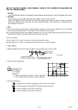


1-6-7
T6605EA
12. Focus Adjustment
Purpose: Set the optimum Focus.
Symptom of Misadjustment: If Focus Adjustment is
incorrect, blurred images are shown on the display.
Note: Focus VR (FBT) --- H.V./Power Supply CBA
FBT= Fly Back Transformer
1. Operate the unit more than 30 minutes.
2. Face the unit to the East and degauss the CRT
using a Degaussing Coil.
3. Input the monoscope pattern.
4. Adjust the Focus Control on the FBT to obtain clear
picture.
13. Head Switching Position Adjustment
Purpose: Determine the Head Switching Position dur-
ing Playback.
Symptom of Misadjustment: May cause Head
Switching Noise or Vertical Jitter in the picture.
Note: Unit reads Head Switching Position automati-
cally and displays it on the screen (Upper Left Corner).
Manual Adjustment
1. Enter the service mode. (See page 1-6-1.)
2. Playback the test tape (FL6A).
3. Press the number [5] button on the remote control
unit.
4. The Head Switching position will display on the
screen; if adjustment is necessary follow step 4.
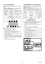
7.0H (448
µ
s) is preferable.
5. Press [PROG+/PROG-] buttons on the remote con-
trol unit if necessary. The value will be changed in
0.5H steps up or down. Adjustable range is up to
9.5H. If the value is beyond adjustable range, the
display will change as:
Lower out of range: 0.0H
Upper out of range: -.-H
6. Turn the power off and on again.
Auto Adjustment
1. Load the test tape (FL6A) that have been recorded
the Head Switching Position Value.
2. Enter the service mode.
3. Press [3] button on the remote control unit in the
tape stop mode. The unit playback and adjust the
Head Switching Position automatically.
4. The adjusting report appears on upper left corner
of the screen with blueback.
In case of adjusting correctly: the Head Switching
Position Value recorded in the test tape (FL6A) is
indicated with green.
In case of adjusting incorrectly: "NG" (red) is indi-
cated with ejecting tape.
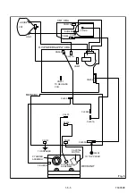
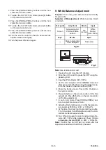
l
Test point
Adj. Point
Mode
Input
Screen
Focus Control
RF
(or Ext.)
Monoscope
Tape
M. EQ.
Spec.
---
Pattern Generator
See below.
NG
Incorrect
7.0H
Correct
TVCR
TVCR
Fig. 7
Содержание T6605VF
Страница 17: ...1 5 4 T6605DC Fig 4 S 10 S 10 S 10 S 10 Anode Cap 10 CRT CRT CBA...
Страница 22: ...1 5 9 T6705DC Fig 4 S 10 S 10 S 10 S 10 Anode Cap 10 CRT CRT CBA...
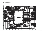
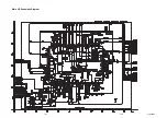
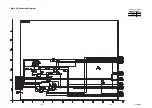
Страница 41: ...Main 1 5 Schematic Diagram 1 8 3 1 8 4 T6605SCM1...
Страница 42: ...Main 2 5 Schematic Diagram 1 8 5 1 8 6 T6605SCM2...
Страница 64: ...1 14 5 T6605PEX Packing T6605VF S3 S6 X3 S2 X4 X1 TAPE S1 FRONT S4 X2 3...
Страница 65: ...1 14 6 T6605PEX T6705VF S3 S6 X3 S2 X4 X1 TAPE S1 FRONT S4 X2 3...
Страница 99: ...2 4 9 Z13PDA Fig DM16 43 41 42 L 13 Fig DM17 44 45 Slide P 9...
Страница 106: ...T6605VF T6705VF T6605VF T6705VF 2004 03 29...


