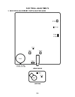
Durabrand DBVT1341 Скачать руководство пользователя страница 54

D1-3

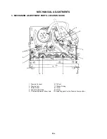
MECHANICAL ADJUSTMENTS

2-3:

2-2:

When the Tape Running Mechanism does not work well,
adjust the following items.

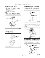
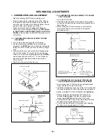
CONFIRMATION AND ADJUSTMENT OF AUDIO/
CONTROL HEAD

1.

2.

3.
4.

When the height is not correct, turn the screw 

3

 to

adjust the height. Then, adjust the 1~3 again.

Playback the VHS Alignment Tape (JG001 or JG001B).
(Refer to SERVICING FIXTURE AND TOOLS)
Confirm that the reflected picture of stamp mark is
appeared on the tape prior to P4 Post as shown in Fig.
2-2-A
.
a)

b)

Turn the screw 

2

 to set the audio level to maximum.

Confirm that the bottom of the Audio/ Control Head and
the bottom of the tape is shown in Fig. 2-2-C.
c)

When the reflected picture is distorted, turn the screw

1

 clockwise until the distortion is disappeared.

When the reflected picture is not distorted, turn the
screw 

1

 counterclockwise until little distortion is

appeared, then adjust the a).

P4 Post

Fig. 2-2-A

Audio/Control Head

1

3

2

Fig. 2-2-B

Audio/Control Head

Fig. 2-2-C

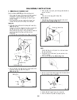
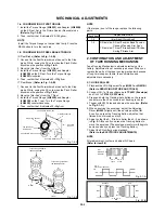
TAPE RUNNING ADJUSTMENT
(X VALUE ADJUSTMENT)

Confirm and adjust the height of the Reel Disk.
(Refer to item 1-1)
Confirm and adjust the position of the Tension Post.
(Refer to item 1-2)
Adjust the Guide Roller. (Refer to item 2-1)
Confirm and adjust the Audio/Control Head.
(Refer to item 2-2)
Connect CH-1 of the oscilloscope to TP4001, CH-2 to
TP1002 and CH-3 to HOT side of Audio Out Jack.
Playback the VHS Alignment Tape (JG001S or
JG001T)
(Refer to SERVICING FIXTURE AND TOOLS)
Press and hold the Tracking-Auto button on the remote
control more than 2 seconds to set tracking to center.
Set the X Value adjustment driver (JG153) to the 

4

 of

Fig. 2-2-B. Adjust X value so that the envelope waveform
output becomes maximum. Check if the relation between
Audio and Envelope waveform becomes (1) or (2) of Fig.
2-3
.

1.

2.

3.
4.

5.

6.

7.

8.

4

Audio/Control Head

Reflected picture of
Stamp Mark

Stamp Mark

Tape

0.25

±

0.05mm

Envelope

CH-3
Audio

(1)

(2)

Fig. 2-3

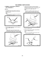
2-4: CONFIRM HI-FI AUDIO (Hi-Fi model only)

Connect CH-1 of the oscilloscope to TP1002 and CH-2 to
the Hi-Fi Audio Out Jack.
Playback the VHS Alignment Tape (JG001P or JG001Q).
(Refer to SERVICING FIXTURE AND TOOLS)
Press and hold the Tracking-Auto button on the remote
control more than 2 seconds to set tracking to center.
Press the Tracking Up button and count number of steps
which the audio output is changed from Hi-Fi (10KHz) to
MONO (6KHz).
Press and hold the Tracking-Auto button on the remote
control more than 2 seconds to set tracking to center.
Press the Tracking Down button and count number of
steps which the audio output is changed from Hi-Fi
(10KHz) to MONO (6KHz).
If the difference are more than 3 steps, set the X Value
adjustment driver (JG153) to 

4

 of Fig. 2-2-B. Change the

X Value and adjust it so that the value becomes within 2
steps.

1.

2.

3.

4.

5.

6.

7.

Содержание DBVT1341

Страница 1: ...SERVICE MANUAL Design and specifications are subject to change without notice DBVT1341 Series A COLOR TELEVISION VIDEO CASSETTE RECORDER ORIGINAL MFR S VERSION B...

Страница 2: ...SERVICE MANUAL Please file this revision with the original version COLOR TELEVISION VIDEO CASSETTE RECORDER REVISION 1 MFR S VERSION B DBVT1341 MFR S VERSION A B IC4001 LA71200M MPB LA71201M MPB...

Страница 3: ...100K OHM 1 10W R801R7474J RC 470K OHM 1 10W R4050 R903N8473J RC 47K OHM 1 8W DEL R4052 R903N8682J RC 6 8K OHM 1 8W R903N8822J RC 8 2K OHM 1 8W R4053 R903N8562J RC 5 6K OHM 1 8W R903N8682J RC 6 8K OHM...

Страница 4: ..._ST_H Y C_CLK CYL_DRIVE Y C_DATA Y C_CS P CON 5V H SW RENT_H SD_VIDEO PGIN X_RAY ENV_DET VCR_A_MUTE PGIN CTL CTL C_ROTARY DUMMY_V SYNC CYL_PG VCR_A_MUTE TAB_SW V REC_ST_H H AMP_SW1 CYL_FG TV_A_MUTE CO...

Страница 5: ...M578 05A K175001 SPEC NO O R NO...

Страница 6: ...02 323 508 341 331 334 333 314 302 301 313 307 300 317 309 336 346 345 321 319 320 AB 316 318 325 347 AA AB AB AB AA AA AA AA AA AB AB AB AB AB AB AB AB Applying positions AA and AB for the grease are...

Страница 7: ...505 510 338 510 337 340 509 308 344 327 343 326 328 AA AA AB AB AB AA AA AA AA AA AA AA AA AA Applying positions AA and AB for the grease are displayed for this section Check if the correct grease is...

Страница 8: ...0 723000A823 FILM DECORATION 121 735WPDA523 BUTTON FRAME 122 743WKA0032 SPRING FLAP COMBO 123 7220001119 SHEET CSA WARNING 124 755WPA0026 PLATE COVER LIGHT 125 722000A023 SHEET HWC 201 8117540B04 SCRE...

Страница 9: ...5 ARM ASS Y 2 H5002 1543D02013 HEAD FULL ERASE HVFHP0032A 314 85OA400233 TENSION ARM ASS Y WT M101 1596P98001 MOTOR LOADING MXN13FB12K3 315 85OA400231 INCLINED BASE S UNIT M2001 1510S98036 CAPSTAN DD...

Страница 10: ...00 FET STP5NC50FP C801 C0PWB07H3K CC 0 0022UF 2KV B Q511 TCAT032034 TRANSISTOR SILICON KTC3203_Y AT DIODES Q601 T6YJ1037K0 TRANSISTOR SILICON 2SA1037AKT146R S D401 D2WT011E10 DIODE SILICON 11E1 EIC Q6...

Страница 11: ...97 0504101T34 SWITCH TACT EVQ21505R CMP METAL POLYESTER CAPACITOR SW798 0504101T34 SWITCH TACT EVQ21505R CMPL METAL PLASTIC CAPACITOR SW799 0504101T34 SWITCH TACT EVQ21505R CMPP METAL POLYPROPYLENE CA...

Страница 12: ...M5A3 03C K1Y5017 SPEC NO O R NO...

Страница 13: ...AUDIO SIGNAL REC AUDIO SIGNAL PB RECORD LUMINANCE SIGNAL T4001 1626009 COIL BIAS OSC 1 2 3 4 5 6 IC4001 LA71201M N MPB Y C A CCD H AMP IC 1 10 11 12 13 14 15 16 17 18 19 2 20 21 22 23 24 25 26 27 28 2...

Страница 14: ...TER NOTE THE DC VOLTAGE AT EACH PART WAS POWER_FAIL2 P CON 5V GND SDA SCL OSD_R OSD_G OSD_B REEL_T REEL_S Y C_CS CAP_CTL Y C_CLK CENTLED OSD_BLK SD_SYNC Y C_DATA CYL_DRIVE V REC_ST_H MOTOR 12V GND Y C...

Страница 15: ...ACK MEASURED WITH THE DIGITAL TESTER NOTE THE DC VOLTAGE AT EACH PART WAS AUDIO SIGNAL REC AUDIO SIGNAL PB SOUND_GND SOUND SP_OUT AT 5V INT MONI B OUT IIC_OFF SDA SCL T REC_LED REC_LED GND KEY_B KEY_A...

Страница 16: ...607 220 1 2W R668 470 1 4W R612 680 1 4W R616 1K R627 12K R639 12K R663 100 R628 100 R650 470 1 4W R608 10K R631 6 8K R656 1K R624 2K R602 100 R603 100 R613 12K R641 22K R649 2 2K C655 47 16V KA C648...

Страница 17: ...ADCAST WAS RECEIVED IN GOOD CONDITION AND PICTURE IS NORMAL NOTE IC351 AN7511 SOUND AMP IC 1 2 3 4 5 6 7 8 OF PRINTING AND SUBJECT TO CHANGE WITHOUT NOTICE NOTE THIS SCHEMATIC DIAGRAM IS THE LATEST AT...

Страница 18: ...EIC D519 SB290S D514 1SS133 D512 SB290S D507 SB290S B EIC D536 10ELS6N D510_1 RU2AM EIC D505 SB290S D508 1SS133 D533 1SS133 D513 1SS133 D517 10ELS2N D518 RM11C EIC D521 RM11C EIC D537 1SS133 OF PRINTI...

Страница 19: ...1 EIC OF PRINTING AND SUBJECT TO CHANGE WITHOUT NOTICE NOTE THIS SCHEMATIC DIAGRAM IS THE LATEST AT THE TIME C402 1000 35V YK C418 22 50V YK C451 0 22 100V TF C424 0 0091 1 25KV MPP C438 0 001 500V B...

Страница 20: ...PICTURE IS NORMAL NOTE B SIGNAL CP851B B2013H02 10P 1 10 2 3 4 5 6 7 8 9 S801 OF PRINTING AND SUBJECT TO CHANGE WITHOUT NOTICE NOTE THIS SCHEMATIC DIAGRAM IS THE LATEST AT THE TIME C811 470P B C810 4...

Страница 21: ...E PARTS MARKED BY CAUTION THE DC VOLTAGE AT EACH PART WAS MEASURED WITH THE DIGITAL TESTER WHEN THE COLOR BROADCAST WAS RECEIVED IN GOOD CONDITION AND PICTURE IS NORMAL NOTE CD351_1 CH27090A 1 2 3 4 5...

Страница 22: ...V GND CUT OFF R OUT NC NC HEATER H GND G OUT B OUT CRT PCB PCB110 F CRT SOCKET J801 5 4 3 6 7 8 9 1 GND GND V801 H V CRT ANODE NC NC NC NC NC TU601 PACK TUNER IF 30V 5V SDA SCL AGC U IN 11 10 1 3 5 6...

Страница 23: ...IO CCD HEAD AMP 10 PB 1 0V 5ms div 13 PB 1 0V 5ms div 11 PB 0 5V 0 5ms div 8 POWER ON 1 0V 10 s div 9 PB 1 0V 10ms div 6 POWER ON 1 0V 20 s div 2 POWER ON 100mV 0 1 s div 1 PB 0 5V 20 s div 7 POWER ON...

Страница 24: ...50 0V 20 s div The following waveforms were measured at the point of the corresponding balloon number in the schematic diagram NOTE H 2 WAVEFORMS CRT 22 50 0V 20 s div 21 50 0V 20 s div 20 200mV 20 s...

Страница 25: ...MECHANICAL EXPLODED VIEW I 1 205 205 205 205 L503 V801 111 J801 PCB110 CRT PCB 120 PCB030 OPERATION PCB 115 118 113 117 207 206 108 121 101 B 206 SP351 116 122 206 110 207 123 125...

Страница 26: ...MECHANICAL EXPLODED VIEW I 2 114 202 202 202 202 106 202 204 203 207 119 209 204 204 109 104 104 112 112 211 210 211 210 FB401 PCB010 SYSCON PCB 105 201 201 208 102 209 103 107 204 124...

Страница 27: ...602 C1016 C1015 W240 W232 L1001 Q1005 R1016 C1020 W268 W249 X1001 X1002 IC1099 SW1001 W237 W238 W250 W254 W150 CP757_2 W912 W213 Q1013 W257 W173 R4028 W087 Q4006 W112 W111 W108 W107 CP4001_1 W122 W096...

Страница 28: ...1036 C1027 Q1004 C1022 C1025 R1012 C1019 R1013 R1009 C1013 C1071 R1034 R1033 C1038 C1035 C1034 C1031 R1031 R1032 C1046 C1047 C1040 C1048 R1040 C1049 C1050 R1070 R1083 R1087 I C 1 0 0 1 R1052 Q1007 Q10...

Страница 29: ...ther there are the portions which are deteriorated around the serviced places serviced or not Check the insulation between the antenna terminal or external metal and the AC cord plug blades And be sur...

Страница 30: ...S TV Y C AUDIO CCD HEAD AMP MICON OPERATION IN OUT PRINTED CIRCUIT BOARDS OPERATION SYSCON CRT SCHEMATIC DIAGRAMS Y C AUDIO CCD HEAD AMP MICON IN OUT CHROMA IF SOUND AMP POWER DEFLECTION CRT OPERATION...

Страница 31: ...ning System F Synth Input Impedance VHF UHF 75 ohm CH Coverage 2 69 4A A 5 A 1 A I J W W 1 W 84 Intermediate Picture FP 45 75MHz Frequency Sound FS 41 25MHz FP FS 4 5MHz Preset CH No Stereo Dual TV So...

Страница 32: ...ontrol Volume Yes Level Bright Contrast Sharpness Color Yes Tint Yes Bass Treble Balance No Manual Tracking Yes Play Stop FF Rew Rec OTR T Rec Pause Eject Tape In Symbol Mark Yes Auto Tracking Manual...

Страница 33: ...ject Yes VIDEO PLUS SHOWVIEW G CODE No Auto Clock Yes Forward Reverse Picture Search Yes One Touch Playback No Auto CH Memory Yes Closed Caption Yes TV Auto Shut off Function Yes End Call No Index Sea...

Страница 34: ...Video Input RCAx1 Audio Input RCAx1 Other Terminal Head Phone Stereo Mono 3 5mm Rear Video Input No Audio Input No Video Output No Audio Output No Euro Scart No Diversity No Ext Speaker No DC Jack 12...

Страница 35: ...CP502 Unlock the support 2 Remove the TV VCR Block in the direction of arrow Remove the Anode Cap Refer to REMOVAL OF ANODE CAP Disconnect the following connectors CP801 and CP851B Remove the CRT PCB...

Страница 36: ...move the Locker R 1 2 3 Link Ass y NOTE 1 2 In case of the Locker R installation check if the two positions of Fig 2 3 B are correctly locked When you install the Cassette Side R be sure to move the L...

Страница 37: ...2 3 Fig 2 6 A Screw Torque 3 0 5kgf cm Loading Motor 1 Main Chassis Worm NOTE 1 In case of the Worm installation check if the value of the Fig 2 6 B is correct Fig 2 6 B 19 2 0 1mm Safety surface for...

Страница 38: ...ouch the section A of S Reel and T Reel Use gloves Refer to Fig 2 9 A Do not adhere the stains on it When you install the reel clean the shaft and grease it MG 33 If you do not grease noise may be hea...

Страница 39: ...Use gloves When you install the A C Head Spring install as shown in Fig 2 11 B When you install the A C Head tighten the screw 1 first then tighten the screw 2 finally tighten the screw 3 1 2 3 2 10 C...

Страница 40: ...Loading Arm S Unit and Loading Arm T Unit 1 Main Rod Main Loading Gear Tension Lever Loading Arm T Unit Loading Arm S Unit Fig 2 16 A 2 13 AHC ASS Y CYLINDER UNIT ASS Y Refer to Fig 2 13 Unlock the su...

Страница 41: ...Fig 2 18 B Fig 2 18 C Cassette Guide Post Cassette Guide Post 2 17 Remove the Polyslider Washer 1 Remove the Clutch Ass y and Ring Spring Remove the Clutch Lever Remove the Coupling Gear Coupling Spr...

Страница 42: ...p up the sides of the Rubber Cap in the direction of the arrow and remove one side of the support Refer to Fig 3 2 2 DISASSEMBLY INSTRUCTIONS GND on the CRT Screwdriver Alligator Clip Support CRT GND...

Страница 43: ...sing a blower type IC desoldering machine Refer to Fig 4 2 2 Fig 4 2 NOTE Do not add the rotating and the back and forth directions force on the IC until IC can move back and forth easily after desold...

Страница 44: ...8 Thin tip Soldering Iron NOTE When the IC leads are bent during soldering and or repairing do not repair the bending of leads If the bending of leads are repaired the pattern may be damaged So be al...

Страница 45: ...op Frequency Generator Front Loading Switch Frequency Modulation Frequency Sub Carrier Forward Generator Ground High Pass Filter I K L M N O P R S H SW Hz IC IF IND INV KIL L LED LIMIT AMP LM LDM LP L...

Страница 46: ...or Separation Transistor Tracking Trick Playback Test Point Unregulated Volt Voltage Controlled Oscillator Video Intermediate Frequency Vertical Pulse Voltage Display Video Playback Variable Resistor...

Страница 47: ...g to the center position NOTE Also can be adjusted by pressing the ATR button for more than 2 seconds during PLAY VOL MIN 5 POWER ON total hours and PLAY REC total hours are displayed on the screen Re...

Страница 48: ...ith the tape Clean the rubber and parts which the rubber touches Replace when rolling becomes abnormal Clean the Head CONFIRMATION OF HOURS USED POWER ON total hours and PLAY REC total hours can be ch...

Страница 49: ...elow 2 TAPE RUNNING SYSTEM When cleaning the tape transport system use the gauze moistened with isopropyl alcohol 3 CYLINDER Wrap a piece of chamois around your finger Dip it in isopropyl alcohol Hold...

Страница 50: ...9 7C 7E 7F 50 54 5D 5E 5F 60 61 62 60 3 4 5 6 7 8 The unit will now have the correct DATA for the new MEMORY IC Table 1 1 2 Fig 1 ADDRESS is now selected and should blink Using the PLAY or STOP button...

Страница 51: ...s model VHS Alignment Tape For 4 heads model VHS Alignment Tape For 4 heads model VHS Alignment Tape For 4 heads model Adapter Dial Torque Gauge 10 90gf cm Dial Torque Gauge 60 600gf cm Post Adjustmen...

Страница 52: ...Set the unit to the PLAY mode Install the tentelometer as shown in Fig 1 3 Confirm that the meter indicates 20 2gf in the beginning of playback 1 2 USING A CASSETTE TYPE TORQUE TAPE JG100A 1 2 3 After...

Страница 53: ...2 as shown in Fig 2 1 B even if you press the Tracking Button to move the envelope The envelope waveform will begin to decrease when you press the Tracking Button Adjust the PG shifter during playback...

Страница 54: ...to TP4001 CH 2 to TP1002 and CH 3 to HOT side of Audio Out Jack Playback the VHS Alignment Tape JG001S or JG001T Refer to SERVICING FIXTURE AND TOOLS Press and hold the Tracking Auto button on the rem...

Страница 55: ...USTMENT PARTS LOCATION GUIDE 5 6 7 8 9 10 1 2 3 4 1 Tension Connect 2 Tension Arm 3 Guide Roller 4 Audio Control Head 5 X value adjustment driver hole 6 7 8 9 10 P4 Post T Brake Spring T Reel S Reel A...

Страница 56: ...d Switching Pulse becomes 6 5 0 5H Refer to Fig 2 1 A B Press the Tracking Auto button 6 5H 6 5H Fig 2 1 B CH 2 CH 1 CH 1 CH 2 Fig 2 1 A 2 BASIC ADJUSTMENTS 2 2 VCO FREERUN 1 2 3 4 5 6 7 8 9 Place the...

Страница 57: ...utton 10 on the remote control to select R CUT OFF Using the VOL UP DOWN button on the remote control adjust the R CUT OFF Press the CH UP DOWN button on the remote control to select the R DRIVE B DRI...

Страница 58: ...the range between white 100 and 0 is set to 4 scales on the screen of the oscilloscope Press the VOL UP DOWN button on the remote control until the red color level is adjusted to 110 10 of the white...

Страница 59: ...D2 4 ELECTRICAL ADJUSTMENTS 3 ELECTRICAL ADJUSTMENT PARTS LOCATION GUIDE SYSCON PCB TU601 FOCUS VOLUME SCREEN VOLUME FB401 CP351 VR502 TP1001 CP1003 TP4001 TP1002 J801 CRT PCB TP801 TP803 TP601 VR401...

Страница 60: ...erforming adjustments in section 4 1 1 2 3 4 5 Receive the green raster pattern from color bar generator Adjust the pair of purity magnets to center the color on the screen Adjust the pair of purity m...

Страница 61: ...T AT 5V_BACK UP X602 3 579545MHz 53 Q602 Q603 REG Q606 Q604 Q605 F501 14 13 UNREG 8V 1 2 TH501 F502 POWER_FAIL 50 1 E180V 27 TV_POWER H E 1 E 2 HEAD SP SP CD352 J351 FB401 L503 DEGAUSS COIL NC REG REG...

Страница 62: ...MMY_V SYNC SD_VIDEO SD_SYNC TU_VIDEO FRONT_AUDIO Y C_AUDIO 6 2 3 1 5 Q4005 BIAS CTL 11 4 P CON 5V 1 C ROT RF SW IN AUDIO MUTE HA SW ENV DET Q4006 BIAS OSC Q4003 SW Q4001 Q4002 AUDIO PB SW Q4012 BUFFER...

Страница 63: ...W TO 9 5 CAP M F R LDM_CTL 4 CAP_CTL CP1004 1 3 4 2 REEL SENS Q1005 POWER FAIL2 MICON OPERATION IN OUT BLOCK DIAGRAM X_RAY SDA SCL OSD_R CTL SD_VIDEO CTL V REC_ST_H VD OSD_G AFT_M OSD_B OSD_BLK HD Y C...

Страница 64: ...796 SW797 SW751 C382 R351 R350_1 W811 C755_1 R766 R754_2 R793_2 R772_1 W001 R775_1 R776_1 R777_1 J701_1 R773_1 R774_1 R771_1 W002 W003 W004 W005 W006 W007 W008 R778_1 W814 W009 W815 CD352 CD757 CD351_...

Отзывы: