DISASSEMBLY INSTRUCTIONS
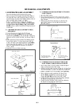
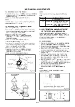
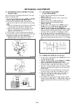
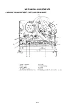
B2-5
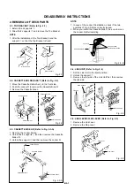
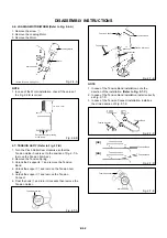
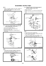
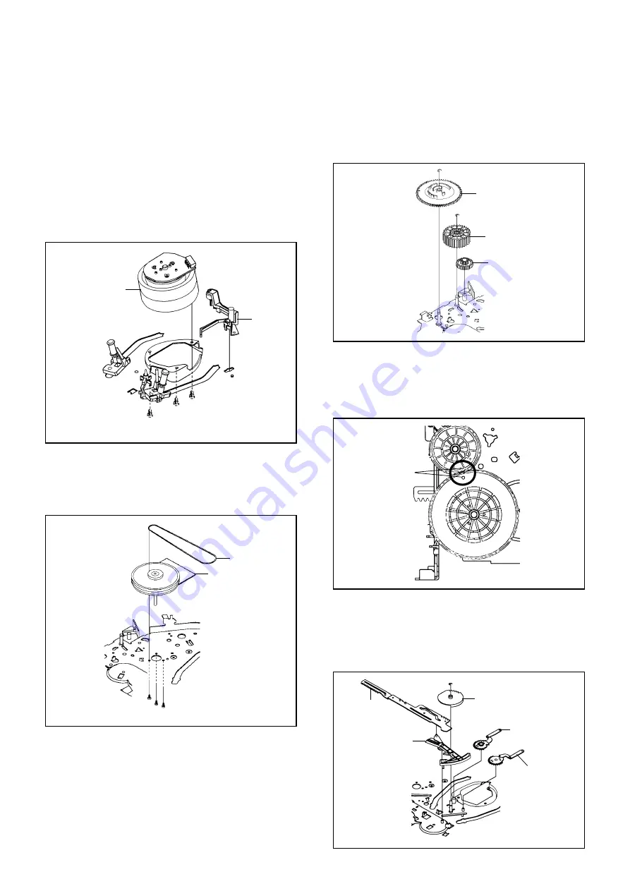
Fig. 2-15-A
NOTE
In case of the Pinch Roller Cam and Main Cam
installation, install them as the circled section of Fig. 2-
15-B so that the each markers are met. (Refer to Fig.
2-15-B)
Fig. 2-15-B
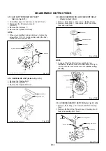
2-15:
Remove the E-Ring
1
, then remove the Main Cam.
Remove the E-Ring
2
, then remove the Pinch Roller
Cam and Joint Gear.
1.
2.
MAIN CAM/PINCH ROLLER CAM/JOINT GEAR
(Refer to Fig. 2-15-A)
1
Main Cam
Pinch Roller Cam
Joint Gear
2
1.
Pinch Roller Cam
Main Cam
Marker
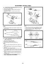
2-16: LOADING GEAR S/T ASS'Y (Refer to Fig. 2-16-A)
1.
2.
Remove the E-Ring
1
and remove the Main Loading
Gear.
Remove the Main Rod, Tension Lever, Loading Arm S
Ass'y and Loading Arm T Ass'y.
1
Main Rod
Main Loading Gear
Tension Lever
Loading Arm T Ass'y
Loading Arm S Ass'y
Fig. 2-18-A
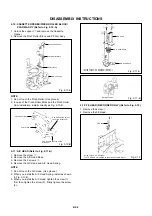
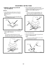
2-13: AHC ASS'Y/CYLINDER UNIT ASS'Y
(Refer to Fig. 2-13)
Unlock the support
1
and remove the AHC Ass'y.
Disconnect the following connector:
(CD2001)
Remove the 3 screws
2
.
Remove the Cylinder Unit Ass'y.
1.
2.
3.
4.
When you install the Cylinder Unit Ass'y, tighten the
screws from (1) to (3) in order while pulling the Ass'y
toward the left front direction.
NOTE
Fig. 2-13
1.
1
AHC Ass'y
Cylinder Unit Ass'y
2
2
2
• Screw Torque: 3
±
0.5kgf•cm
(1)
(3)
(2)
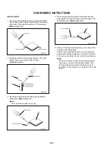
2-14: CAPSTAN DD UNIT (Refer to Fig. 2-14)
Remove the Capstan Belt.
Remove the 3 screws
1
.
Remove the Capstan DD Unit.
1.
2.
3.
Fig. 2-14
• Screw Torque: 4
±
0.5kgf•cm
Capstan DD Unit
Capstan Belt
1
1
1
Содержание DBV4403
Страница 50: ...M4F2 10B O R NO SPEC NO K184002...


