Du line
®
Fieldbus
Installationbus
Specifications are subject to change without notice (12.12.2008)
3
Dupline®
®
is a registered trademark. A product of the CARLO GAVAZZI Group
GP73800080
Mode of Operation (cont.)
not use a “Lane Detector Sensor, dis-
able the address with two crosses
“XX” by pressing the tactile key “8”
If the “Lane Detector Sensor” is select-
ed it is possible to implement an “off
delay” of maximum120 Sec. See Fig.9.
When a Car moves under the “Lane
Detector Sensor” the Carpark system
count down the free number of parking
spaces with one, in the selected
amount of time. When the time runs
out, the Carpark system will go back
to the previous value until next time
the “Lane Detector Sensor” is activat-
ed.
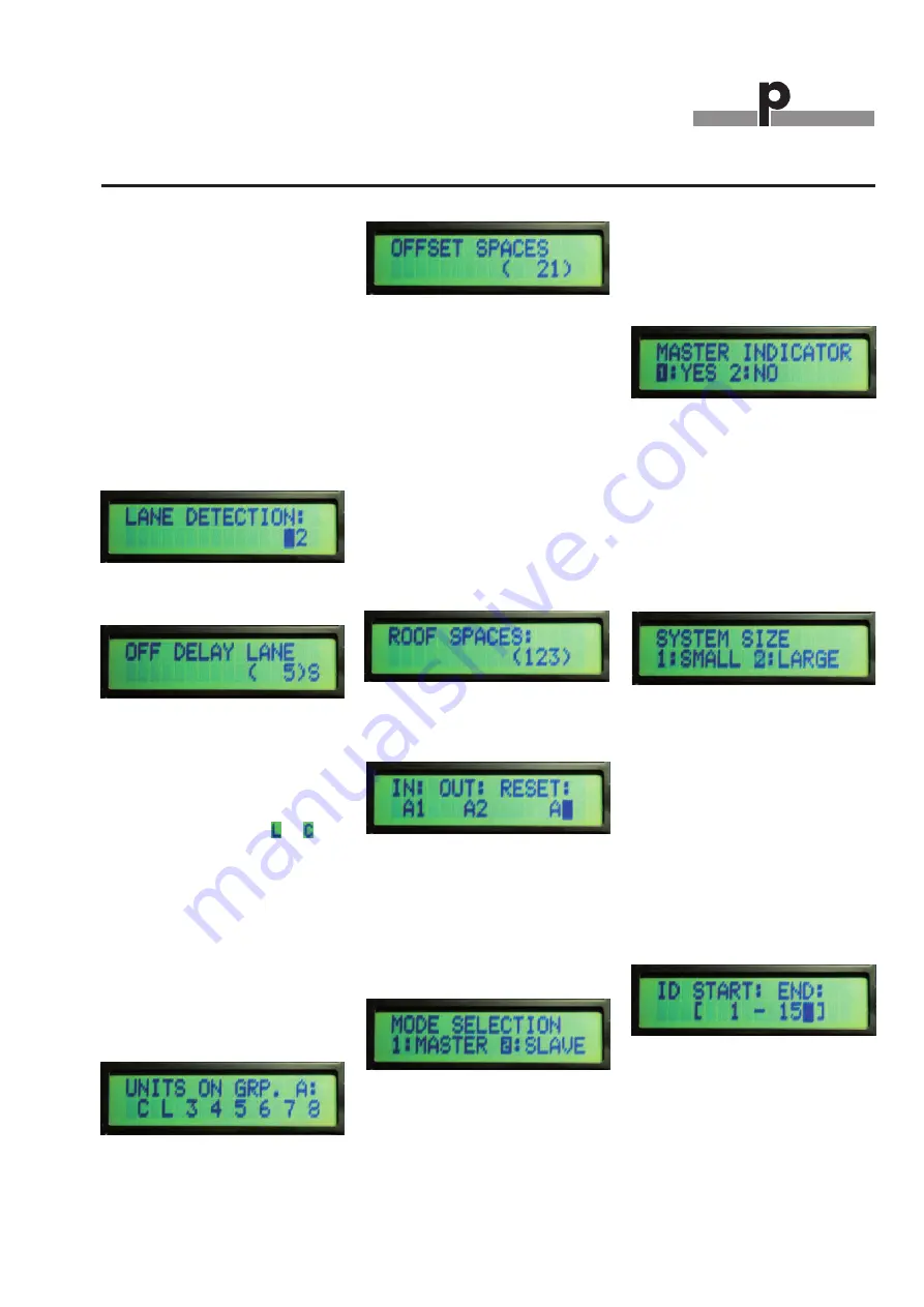
Lane Detection in Slave mode
Fig. 8
Off Delay Lane in Slave mode
Fig.9
The Slave monitors are monitoring the
L1 bus with the maximum of 127 Sen-
sors. In “Units on Grp” (Fig. 10) the
user can see/select the channels for
each connected sensor. If one of the
numbers is replaced with
or
then
the address is occupied for e.g. “Lane
Detector Sensor” or “Calibration”.
The user can implement an “Offset
Space” (Fig.11) from 0 to 10 Cars on
each of the slave monitors. This allows
the system always to have maximum
10 spaces free for each of the slave
monitors. This is to prevent Car jam in
the parking area and offer the user
some extra free spaces.
Select/See channel for each connect-
ed sensor in Slave mode
Fig.10
Offset spaces in Slave mode
Fig. 11
In “Roof mode”, the slave monitor is
able to monitor up to 127 Sensors. At
the entrance of the roof, a sensor
detects each car passing and count
down
the
total
numbers
of
free
spaces. The same happens at the exit,
but here it counts up the total numbers
of free spaces. The Input and the Out-
put sensor are specified with their
Dupline
®
channels. If, for some reason
there is a mismatch with the correct
number of free parking places, then it
is possible to reset the counter, when
the roof is empty (Fig. 13).
Roof Spaces in Slave mode
Fig. 12
In/Out channels and Reset channels in
Slave mode
Fig. 13
Master mode:
The GP3482 9091 724 monitor can
also be used in “Master mode”.
Select Master by press 1 (Fig.14).
Selection between Master and Slave
mode
Fig.14
If the user selects ”NO” in the indicator
mode, then the Master is making the
sync signal for the entire system. It is
only possible to have one Master in a
system. But several Master Indicators.
If “YES” is selected, then the Master is
working as an Master Indicator. That is
the same as the Master but the Master
Indicator cannot generate a sync sig-
nal.
Indicator in Master mode
Fig.15
In both modes the user must select if
the system is a “Small” or a “Large”
system. A small system has less than
240 Slave monitor connected. If a
large system is selected then there are
more than 240 slave monitors con-
nected. Maximum 480 slave monitors
can be connected to the system.
System size in Master mode
Fig. 16
By inserting the ID for the “Start”
address and “End” address, the Mas-
ter (or Master indicator) is able to mon-
itor a specific area in the Carpark sys-
tem. If e.g. 101 and 200 are selected
for the specific Master monitor, then it
is possible to see available parking
spaces in the area from Slave monitor
number 101 to Slave monitor number
200 and all the slave monitors in
between. Then it is possible to see 100
* 127 = 12700 parking places.
ID number in Master mode
Fig. 17
It is possible to select an “Offset
space” for the Master (or Master moni-
tor). The maximum number of “Offset”
is 9999.
The “Offset” is used to prevent Car
jam and to make a smooth parking


