background image

ATT2100 TEMPERATURE TRANSMITTER                                            


Operation Manual   M2100-REV-G


38 

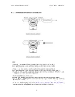
4.13 Temperature Sensor Installation


NOTE 


1. Install per local installation codes. Qualified cable entry or stopping box required. 

(For Using ATEX explosion proof certificate, Must be use ATEX approved cable entry) 


2. Temperature sensor assembly must be qualified for appropriate area classification. 
(For Using ATEX explosion proof certificate, Must be use ATEX approved Temperature sensor) 

3. Threads must be assembled with loctite thread sealant and have a minimum of five full threads 

engagement and 8mm axial length engagement. 


4. Must use qualified temperature sensor.   

(For Using ATEX explosion proof certificate, Must be use ATEX approved Temperature sensor) 
5. It is possible to install temperature sensor both side of housing and bottom of housing considering 

the installation condition. 

 
6. In the case of detecting high temperature (

T6: above 75 

, T5: above 90 

, T4: above 125 

)

use the remote type temperature sensor to prevent the influence to transmitter.

Содержание ATT2100

Страница 1: ...n Manual M2X00 E01H Information on this manual can be changed without an advance notice ATT2100 ATT2200 Smart Temperature Transmitter Operation Manual AUTROL Series Operation Manual M2X00 E01H Duon System Co Ltd AUTROL by DUON SYSTEM Co Ltd www autrol com ...

Страница 2: ... operatation of ATT2100 ATT2200 Smart Temperature Transmitter efficiently Before handling Autrol series device all users have to be fully understand to control or get some technical support Information on this manual can be changed without an advance notice DUON SYSTEM CO Ltd 60 31 Gasan dong Guemchon gu Seoul Korea Tel 82 2 860 7900 www autrol com autrol duon co kr ...

Страница 3: ...S 2 1 UNPACKING 2 2 MODEL AND SPECIFICATIONS CHECK 2 3 STORAGE 2 4 SELECTING THE INSTALLATION LOCATIONS 2 5 WATERPROOFING OF CABLE CONDUIT CONNECTIONS 2 6 RESTRICTIONS ON USE OF RADIO TRANSCEIVER 2 7 INSULATION RESISTANCE TEST AND DIELECTRIC STRENGTH TEST 2 8 INSTALLATION OF EXPLOSION PROTECTED TYPE TRANSMITTER 2 9 EMC CONFORMITY STANDARDS 3 TRANSMITTER FUNCTIONS 3 1 OVERVIEW 3 2 SAFETY MESSAGE 3 ...

Страница 4: ...ZERO POINT ADJUSTMENT PROCEDURE 3 10 COMMISSIONING ON THE BENCH WITH HHT 3 11 LCD MESSAGES 4 INSTALLATION 4 1 OVERVIEW 4 2 SAFETY MESSAGE 4 3 WARNING 4 4 COMMISSIONING ON THE BENCH WITH HAND HELD TERMINAL 4 5 GENERAL CONSIDERATIONS 4 6 ELECTRICAL CONSIDERATIONS 4 7 POWER SUPPLY 4 8 WIRING 4 9 LOOP 4 10 WIRING INSTALLATION 4 11 GROUNDING 4 12 POWER SUPPLY VOLTAGE AND LOAD RESISTANCE 4 13 TEMPERATUR...

Страница 5: ... 1 OVERVIEW 5 2 SAFETY MESSAG 5 3 CHECK OUTPUT 5 4 BASIC SETUP 5 5 DETAILED SETUP 5 6 INFORMATION VARIABLE SETUP 5 7 DIAGNOSITICS AND SERVICES 5 8 CALIBRATION 6 MAINTENANCE 6 1 OVERVIEW 6 2 SAFETY MESSAGE 6 3 HARDWARE DIAGNOSTICS 6 4 HARDWARE MAINTENANCE APPENDIX I ATT2100 SMART TEMPERATURE TRANSMITTER LCD DISPLAY CODE ...

Страница 6: ...is manual at the time of change provided that postponement of revisions will not cause difficulty to the user from a functional of performance standpoint 1 1 Using This Manual The Chapters in this operating manual provide information on installing operating and maintaining devices from the AUTROL Model ATT2100 Samrt Temperature Transmitter The Chapters are organized as follows Chapter 2 Handling C...

Страница 7: ...variables in host is enable to be changed configured and tested calibrated by users For the HART Communication between DC Power Supply and Transmitter has to terminate 250 600 Ohm 1 3 Software Compatibility Autrol Smart Transmitter s software is implemented and complemented if necssary Uses of the transmitter will not be a compatibility software is contained in the host of the HHT Model 275 HART C...

Страница 8: ...peration Manual M2100 REV G 7 1 4 Transmitter Components The components and figure of Autrol Smart Temperature Transmitter ATT2100 is as follow Figure 1 1 Model ATT2100 Transmitter Expoded View Housing Figure 1 2 TRANSMITTER COMPONENTS ...

Страница 9: ...ure etc Quick Reference Manual Step Jog Job Details Instrument 1 Unpacking a Unpack transmitter packing 2 Model and Specifications Check a Make sure whether the delivered transmitter is same as options attached on its nameplate 3 Storage a Places not exposed to water non vibration and non impact area b Ambient temperature 25 deg C and relative humidity 65 RH Sensor Element connection terminal Sens...

Страница 10: ... Mounting and Installation a For mounting transmitter an appropriate bracket should be used b Transmitter should be fixed well against swing Mounting and Installation 9 Calibration on Spot a Input mV value at 0 and compensation RTD 100Ω TC according to sensor type 0 mV value b Make sure that PV value of transmitter is zero and current is 4 mA HHT Galvanometer 10 Opeation a Make sure whether transm...

Страница 11: ...sphere If the transmitter must be installed in a corrosive atmosphere there must be adequate ventilation as well as measures to prevent intrusion or stagnation of rainwater in conduits Moreover there should be appropriate ventilation preventing corrosion by rain gathered on conduit 3 Shock and Vibration Select an installation site suffering minimum shock and vibration although the transmitter is d...

Страница 12: ...be applied short as possible to verify that insulation resistance is at least 20MΩ d After completing the test and being very careful not to touch exposed conductors disconnect the insulation tester and connect a 100kW resister between the grounding terminal and the short circuiting SUPPLY terminals Leave this resistor connected at least three second to discharge any static potential Do not touch ...

Страница 13: ... 4 ATT2100 ATEX Certification is according to the below standards EN 60079 0 2006 EN 60079 1 2007 Note 5 Installation All wiring shall comply with local installation requirement The cable glands and blanking elements shall be of a certified flameproof type suitable for the condition of use and correctly installed Also those devices should be endured at the 130 C Housing Ground must be followed to ...

Страница 14: ...Ignition proof for Class II Division 1 Groups E F and G Dust ignition proof for Class II Division 1 T6 see instruction for temperature code if process temperature above 85 Ambient Temperature 20 to 60 Enclosure indoors and outdoors NEMA Type 4X Conduit seal required within 18 for Group A only Nonincensive for Class I Division 2 Groups A B C and D Class II Division 2 Groups E F and G Class III Divi...

Страница 15: ... or serious injury Do not remove the transmitter covers in explosion environments when the circuit is alive Check transmitter to install accroding to Intrinsically safe regulation before HHT connect to Transmitter in explosive environment Transmitter covers must be fully engaged to meet explosionproof requirements Warning Electrical can result in death serious injury The qualification which is edu...

Страница 16: ...POWER 3 4 Connection of Sensor ATT2100 Temperature Transmitter can input sensors such as RTD Thermocouple TC and Resistance In case RTD 2Wire 3Wire and 4Wire Sensor connection is applicable Also 2Wire TC B E J K N R S T Sensor input is applicable Below pictures are present sensor connections using RTD TC Ex In case RTD 3Wire common line connect to terminal No 1 2 Figure 3 1 ATT2100 Temperature Tra...

Страница 17: ...1 for Output values Table 3 1 Standard Alarm and Saturation Value Fail Mode Select Jumper Switch has in LCD Module and Main CPU Module and Jumper Switch Line is connected circuital In case of Not LCD Module we can use CPU Module s Fail Mode Select Jumper Switch and In case of LCD Module we can use LCD Module s Jumper Switch In this case CPU Module is selected Down side No selected we can select Do...

Страница 18: ... Mode Switch There is the EEPROM Electrically Erasable Programmable ROM restoring various configuration variables in Transmitter For protect to change configuration variable data in software hardware side there is Write Protect Mode and Jumper Switch selected it segmented EEP Write DIS EN in Main CPU Module Thus if you connect Jumper to DIS you can t change configuration data in EEPROM when you co...

Страница 19: ... Switch There are two security methods in ATT2100 Following this 1 Security Jumper protect to writing configuration parameters of transmitter 2 Physical removing Zero and Span Magnetic Buttons of Transmitter you are not able to regulate Zero and Span in Local 3 6 1 Security Jumper EEPROM Write Protect Protect to change Configuration Parameter of transmitter to Write Protect Jumper CPU Module Jumpe...

Страница 20: ...ng chapter 4 Refer to 275 Hart Communicator User Guide on Appendix II for details Zero Span configuration process by Zero Span Button of transmitter is following this 1 Release to both sides bolts of Name Plate in the upper part of transmitter and if push down right of Name Plate appear to Zero Span Button following figure 3 5 2 Zero Configurations Set the current process value for Lower Range Val...

Страница 21: ...V_raw Value that transmitter calculates signal from sensor PV Value that transmitter finished Sensor Zero Trim or Zero Point Adjustment Offset Value calculated when Sensor Zero Trim or Zero Point Adjustent is done PV PV_raw Offset a In case Sensor Zero Trim PV 0 PV_raw Offset In result Offset PV_raw b In case Zero Point Adjustment PV PV_raw Offset Offset is variable Therefore PV value and Zero poi...

Страница 22: ...h Zero Span button over 3 seconds or do not push any button over 30 seconds Zo message shows in LCD window By this message all procedures finish Range for Zero Point Adjustment is permitted within 100 of Calibrated Span 3 Close cover of Name Plate and lock both bolts Figure 3 4 Transmitter s Zero Span configuration Button Refer to Appendix I for Button Error and LCD Display Message Zero Span Butto...

Страница 23: ...U RNG zero 23 L RNG 24 DAMP 31 LCD MD zero span span zero Zero Trim Zero Adjustment Change Unit Change Upper Range Value Change Lower Range Value Damping Second Change LCD Mode span span span span span span span zero 32 DEC PL Decimal Place span zero zero 25 S TYPE Change Sensor Type T C span 251 T C 252 RTD zero span zero 2521 DIN zero zero 2522 US zero 2523 NI span Change Sensor Type RTD DIN spa...

Страница 24: ...re of after installation If you connect TEST pin it s not communicated If it doesn t exposed electronics circuits after install you must connect all Jumper of transmitter in the shop commissioning level Analog output of transmitter is 4 20 mA thus it requires Power Supply at 11 9 V 45 Vdc ATEX 11 9 to 42Vdc and Ampere meter for measuring output current You must connect 250 550 ohm resistor in Powe...

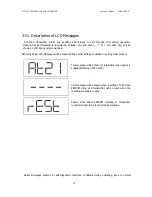
Страница 25: ...enerally below LCD Messages will be shown during nornal working condition or setting inner menory This message will be shown at initial time when power is supplied Meaning of ATT 2100 This message will be shown when resetting of CPU inner EEPROM Data and transmitter will be reset when the resetting procedure is done Shown when above EEPROM resetting or Transmitter reoperation according to reoperat...

Страница 26: ...ing and back to normal condition when the failures are removed Shown when occur inner failure of transmitter operation and back to normal condition when the failures are removed Shown when inner parameter s data error back to normal condition when the failures are removed Shown when set abnormal sensor type and back to normal condition when the failures are removed Shown the polling address when m...

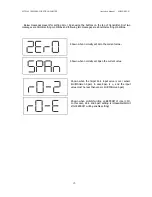
Страница 27: ...ages are abnormal setting conditions Shown when normally set Zero the current value Shown when normally set Span the current value Shown when the target Zero input value is over sensor limit Minimun Span in case Span is and the input value must be less than sensor limit Minimun Span Shown when prohibit writing on EEPROM of inner CPU In this case Zero and Span setting is impossible Permit after EEP...

Страница 28: ...mitter covers in explosion environments when the circuit is alive Check transmitter to install accroding to Intrinsically safe regulation before HHT connect to Transmitter in explosive environment Check environment is fully engaged to the transmitter s harzadous location certificate Both transmitter covers must be fully engaged to meet explosionproof requirements Warning Electrical can result in d...

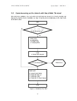
Страница 29: ...nowing the function before installation you have to handle upon commissioning on the bench with Hand Held Terminal Figure 4 1 Installation Flow Chart Start Field Install a Jumper Switch Setup b Transmitter take up c Transmitter leads e Transmitter for Power Supply End Do you want Bench Calibration Basic Setup a Unit Setup b Range Setup c Damping Setup Verify a Temperature Support Yes No Do you sat...

Страница 30: ...Configurator supported HART connects to COMM pin in Power Supply downside In the field Indicator connects to TEST pin 4 7 Power Supply In the transmitter s power supply Input Current Voltage is currently DC voltage between DC 11 9 volt 45 volt and power supply s ripple is not up to 2 Loop resistance means all resistor sums in loop In case of using Intrinsic Safety Barrier same includes resistor of...

Страница 31: ...he power supply in the terminal indicated PWR left terminal and power supply in the central terminal Don t connect power supply in terminal of the point indicated TEST It will be damage to test diode used to connecting TEST terminal 3 Seal and close the non using Conduit Connection Part for severe humidity and explosion on the terminal box of housing 4 Transmitter power is supplied to Signal Wirin...

Страница 32: ... not remove the transmitter covers in explosion environments when the circuit is alive Before connection HHI in explosion zone confirm that the configure device has to be installed by intrinsic safety regulations Check environment is fully engaged to the transmitter s harzadous location certificate Both transmitter covers must be fully engaged to meet explosion proof requirements ...

Страница 33: ...mission DC Power Supply is required for the transmitter loop The Transmitter and distributor are connected as shown below 1 Non Explosionproof Flameproof Type Hazardous Location Nonhazardous Location Transmitter terminal box Distirbutor Receive Power supply unit Instrument 2 Explosionproof Type Hazardous Location Nonhazardous Location Transmitter terminal box Distirbutor Receive Power supply unit ...

Страница 34: ...inner Loop Hazardous Location Nonhazardous Location Transmitter terminal box Distirbutor Receive Power supply unit Instrument Safety barrier 4 10 Wiring Installation 1 General use Type and intrinsically Safe Type make cable wiring using metallic conduit or Waterproof cable glands Saftey Barrier must be connected to inner Loop ...

Страница 35: ...A flameproof type see Figure 4 4b Use only flameproof packing adapter by KOSHA Apply a non hardening sealant to the terminal box connection port and to the threads on the flameproof packing adapter for waterproofing Mounting flameproof packing adapter to the terminal box o Screw the flameproof packing adapter into the terminal box until the O ring touches the terminal box wiring port at least 5 fu...

Страница 36: ...Flameproof metal conduit wiring A seal fitting must be installed near the terminal box connections port for a sealed construction Apply a non hardening sealant to the threads of the terminal box connection box flexible metal conduit and deal fitting for waterproofing ...

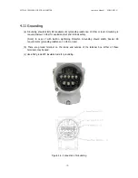
Страница 37: ...low 10 Ohm for explosionproof and intrinsic safety Note In case of with Built in Lightening Protector Grounding should satisfy Special KS requirements grounding resistance 10 Ohm or less b There are ground terminal on the inside and outside of the terminal box Either of these terminals may be used c Use 600V grade PVC insulated wire for grounding Figure 4 4 Connection of Grounding ...

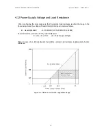
Страница 38: ...ange in the figure below Since the voltage of transmitter terminal input is same as follows General Standard 11 9 to 45 Vdc for the ATEX 11 9 to 42Vdc And maximum loop current is 24mA Load resistance R R E 11 9 0 022 E Power Supply Voltage Note In case of an intrinsically safe transmitter external load resistance includes safety barrier resistance Figure 4 5 HART Communication Applicable Range ...

Страница 39: ... Must be use ATEX approved Temperature sensor 3 Threads must be assembled with loctite thread sealant and have a minimum of five full threads engagement and 8mm axial length engagement 4 Must use qualified temperature sensor For Using ATEX explosion proof certificate Must be use ATEX approved Temperature sensor 5 It is possible to install temperature sensor both side of housing and bottom of housi...

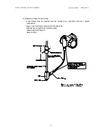
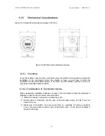
Страница 40: ...e case of severe vibration promote to mount on pipe using a mounting bracket as option 4 14 2 Consideration of Transmitter Access When selecting the establishment location or a place of the transmitter it treats the transmitter it probably is a location that is convenient must consider Rotation of housing housing can be rotated up to 90 Terminal sides of transmitter location ease us terminal space...

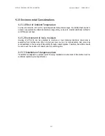
Страница 41: ...vironment of toxic moisture Housing of ATT 2100 can be protected to moisture or toxic material Electronic circuit side is separating from terminal side When O ring Seal cover covers it is intrinsic safety But some drip could penetrate to the housing of transmitter through conduit pipeline Therefore transmitter should be set up over the position of conduit pipe for preventing drip 4 15 3 Installati...

Страница 42: ...r covers in explosion environments when the circuit is alive Before connecting HHT in explosion zone confirm that the configure device has to be installed by intrinsic safety regulations Both transmitter covers must be fully engaged to meet explosion proof requirements Warning Electrical shock can result in death or serious injury If you install high voltage environment or false condition power li...

Страница 43: ... measure is depended Range Code of sensor This value is classified from Temperature sensor module automatically 5 5 2 Set Output Units Select from the following engineering units Unit C F R K etc 5 5 3 Rerange Set the Zero and Span of 4 20mA analog output 5 6 Detailed Setup 5 6 1 Set Fail Mode When sensor is wrong or microprocessor of transmitter doesn t operate normally in order to outputs curren...

Страница 44: ...oop Test The Loop Test verifies the output of the transmitter the integrity of the loop and the operations of any recorders or similar devices installed loop Perform the following procedure for a loop test Connect a reference meter to the transmitter Select the Loop Test of HHT and operate the Loop Test Select output current 4mA 20mA etc If the readings match then the transmitter and the loop are ...

Страница 45: ...Rerange functions provides ability to readjust the 4 20mA points sensor inputs 5 9 1 Sensor Trim The Sensor Trim the transmitter sensor input signal convert A D to lead and how it interprets the values which it inputs with digital the contents of such interpretation and it is regarding to change is connected actually in the sensor which in order to correspond There are three waysto trim the sensor...

Страница 46: ...onnecting HHT in explosion zone confirm that the configure device has to be installed by intrinsic safety regulations Both transmitter covers must be fully engaged to meet explosion proof requirements Warning Electrical shock can result in death or serious injury If you install high voltage environment or false condition power line and lead will be apprered high voltages Avoid contact with the lea...

Страница 47: ...y Check the output voltage of the power supply at the transmitter terminals It should be 11 9 to 45 Vdc in spite of loop scale Electronics Module Connect HHT and enter the Transmitter test mode to isolate module failure Check the sensor limits to ensure calibration adjustments are within the sensor range Erratic Output Loop Wiring Check the output voltage of the power supply at the transmitter ter...

Страница 48: ...ON System Co Ltd for inspection repair or replacement 6 4 1 Test Terminals The test terminal marked as TEST on the terminal block The test and negative terminals are connected to the test terminals so long as the voltage across the receptacles is kept below the diode threshold voltage no current passes through the diode To ensure that there is no leakage current through the diode while making a te...

Страница 49: ...re sealed in a moisture proof plastic enclosure referred to as the electronics module The module is a non repairable unit if a malfunction occurs the entire unit must be replaced 1 Disconnect the power to the transmitter 2 Remove the cover from the electronics side of the transmitter housing Figure 6 2 Do not remove the instrument cover in explosive atmospheres when the circuit is alive Remove the...

Страница 50: ...d front of electronics module Refer to Figure 2 2 2 3 6 4 3 Assembling the Electronics Housing 1 Re assembling procedure is same as follows 1 Make sure that Fail mode and Jumper Switch are set exactly 2 Insert electronics module in housing 3 Firstly connect the connector of sensor board with power connector Mis connection of the two connectors cause wrong output 4 20mA and effect on power of Trans...

Страница 51: ...ATT2100 TEMPERATURE TRANSMITTER Operation Manual M2100 REV G 50 2 Connections of Sensors Connections with Sensors Thermocouple RTD are as follows ...

Страница 52: ...over tr Trim Done sper Setting Limit Error When Button Input 2e Zero Button Function Done sp Span Button Function Done 20 Zero Trim or Zero Adjustment Done F RS Flash Configuration Data Reset F FL Flash Reset Failure FR Flash Reset Done A RS Analog EEPROM Initializing Start A CP Analog EEPROM Copy A FL Analog EEPROM Copy Failure AC Analog EEPROM Copy Done s fl Sensor Fail s op Sensor over pressure...

Отзывы: