APT3500 Smart Pressure Transmitter
Operation Manual M3500-EO1G
63 DUON System Co., Ltd.
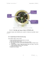
6.4.2.2 Fail Mode and Jumper Switch of EEPROM-write
Fail-mode and jumper switch of EEPROM-write is located front of electronics module(Refer to Figure
2-2, 2-3)
6.4.3 Assembling the Electronics Housing
Re-assembling procedure is same as follows.
1.
Make sure that Fail-mode and Jumper Switch are set exactly.
2.
Insert electronics module in housing
3.
Firstly, connect the connector of sensor board with power connector.
Mis connection of the two connectors cause wrong output(4~20mA) and effect on power
of Transmitter.
In case of power connector sandwitched between board and housing, it may cause
wrong output signal and effect on power of transmitter.
4.
Fix electronics module with 3 screws.
5.
Close the cover of housing..
Figure 6.3 Structure of Electronics Module inner Transmitter
MCU &
Power Module
Analog
Connector
Power(24Vdc)
Connector


