Dunkirk XEB II Series Скачать руководство пользователя страница 17

17

C.  For Flex-L StaR-34 stainless steel vent pipe use 

a high temperature silicone sealant rated for 

550°F. Before applying silicone, the outside of 

the male end and inside of the female end of the 

pipe must be cleaned using a cleaner, such as 

methyl ethyl ketone (MEK) or naphtha. For 3” 

vent pipe runs, begin with the male end of the 

vent pipe over the boiler’s induced draft blower 

outlet. For 4” vent pipe runs begin with a StaR-34 

3” to 4” increaser 

fi

 tting over the boiler’s induced 

draft blower outlet. For both 3” and 4” vent pipe 

runs, apply a bead of silicone sealant around the 

blower outlet and around the  inside of the male 

end of vent pipe going over the blower’s outlet.                                                                                            

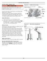
When using the Tjernlund VH-1 vent hood, 

the female end (

fl

 ared end) of the vent pipe 

will be connected to the termination hood.                                                                             

Apply high temperature silicone in an even ¼” 

bead approximately ¼” from the end of the vent 

hood’s connecting vent pipe. Also, run a similar size 

bead of silicone sealant down the seam weld of the 

vent pipe. Then push the female end over the vent 

hood’s connecting vent pipe. Now 

fi

 ll in the channel 

inlet with silicone sealant. Do not try to insert the 

joiner band, instead fasten the vent pipe to the 

vent hood’s pipe with a steel gear clamp.
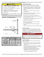
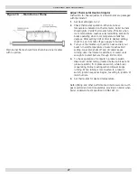
1.  Apply the high temperature silicone around 

the male end of the pipe in an even ¼” bead. 

Silicone bead should be approximately ¼” from 

the end of the male end. Also, run a similar size 

bead of silicone sealant down the seam weld at 

the end of each joint.

2.  The seams on the vent pipe should be aligned 

and oriented upward in all horizontal vent pipe 

runs.

3.  Insert the male end of one into the female end 

of the other. Push the pipe together so the 

female end rests up against the stop bead of the 

male end.

4.  Insert a StaR-Joiner Band into the inlet of the 

beaded channel. Feed the Joiner Band in so 

it makes its way around the pipe, back to the 

channel inlet and it overlaps itself by about ½”.

5.  Cut the excess Joiner Band so it lays 

fl

 at in the 

beaded channel. Fill the inlet of the beaded 

channel with high temperature silicone. Smooth 

out the silicone over the channel inlet and the 

silicone between the female end and the stop 

bead of the male end.

6.  Horizontal venting shall have a slope not less 

than ¼” every 12 inches (21mm/m) downward 

away from the boiler to prevent collection of 

condensate throughout the assembly.

7.  Allow the sealant to cure for 24 hours before 

operating the appliance.

D.  For ProTech Systems FasNSeal stainless steel 

vent pipe no cleaning 

fl

 uid is required. For 3” 

vent pipe runs on 2, 3, 4 and 5 section boilers, 

begin by locating the FasNSeal Ametek Adapter 

over the boiler’s induced draft blower. Continue 

the vent pipe run with 3” FasNSeal vent pipe.                                                                                           

For 6 and 7 section boilers, begin by locating the 

FasNSeal Ametek Adapter over the boiler’s induced 

draft blower. Then connect a FasNSeal 3” to 4” 

increaser to the 3” adapter outlet. Continue the 

vent pipe run with 4” FasNSeal vent pipe. Other 

than the Ametek Adapter and increaser 

fi

 tting, DO 

NOT use 3” vent pipe on 6 or 7 section boilers. 

FasNSeal vent pipe is joined and sealed by the 

use of an internal sealing gasket and a locking 

band on the female end of each vent pipe. All 

components should be examined for possible 

shipping damage prior to installation. Align all vent 

pipe seams and orient upward in all horizontal 

applications. Adjustable vent lengths are available 

for 4” diameter vent piping. For 3” diameter vent 

piping, square cut male end at the desired length. 

For 2, 3, 4 and 5 section boilers using the VH-1-

3” vent hood, connect the FasNSeal Vent to the 

VH-1-3” vent hood using FasNSeal Adapter #FSC-

DUN-3. This adapter has no internal sealing gasket.                                                                      

To attach the adapter to the vent hood, crimp 

the 3” vent hood pipe, apply a ¼” bead of high 

temperature silicone sealant around the outside 

of the vent hood’s crimped connecting pipe and a 

similar bead of high temperature silicone around 

the inside of the FasNSeal adapter. After pressing 

the two pipes together and tightening the locking 

band, 

fi

 nish creating a complete seal by 

fi

 lling 

the FasNSeal adapter’s notched hole with high 

temperature silicone.      For  6 and 7 section 

boilers using the VH-1 - 4” vent hood, an adapter 

is not required. The 4” FasNSeal vent pipe connects 

directly to the VH-1- 4” vent hood, and is joined 

and sealed by the internal gasket and locking band.

To join and seal the FasNSeal vent pipe:

1.  Insert male end into female section.
2.  Push the units together as far as possible.
3.  Firmly tighten locking band with a nut driver.
4.  DO NOT penetrate the FasNSeal vent pipe with 

fasteners.

5.  Horizontal venting shall have a slope of not less 

than ¼” every 12 inches 21mm/m) downward 

away from the boiler to prevent the collection of 

condensate throughout the assembly. 

HORIZONTAL VENTING INSTRUCTIONS   

Содержание XEB II Series

Страница 1: ...LLATION OPERATION MAINTENANCE MANUAL P N 240009020 Rev B 04 2012 Manufactured by ECR International Inc 2201 Dwyer Avenue Utica NY 13501 web site www ecrinternational com Models XEB 2 XEB 3 XEB 4 XEB 5...

Страница 2: ...is boiler must be performed by a qualified installer TO THE INSTALLER Leave all instructions with boiler for future reference When this product is installed in the Commonwealth of Massachusetts the in...

Страница 3: ...upon Net AHRI Rating being equal to or greater than calculated heat loss of building Manufacturer should be consulted before selecting a boiler for installations having unusual piping and pickup requi...

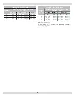
Страница 4: ...4 DIMENSIONS Model Width A XEB 2 11 XEB 3 14 1 4 XEB 4 17 1 2 XEB 5 20 3 4 XEB 6 24 XEB 7 27 1 4...

Страница 5: ...ting installation See rating and capacity table 8 When installed in utility room door should be wide enough to allow largest boiler part to enter or to permit replacement of another appliance such as...

Страница 6: ...s communicating directly or by ducts with outdoors Two Permanent Opening Method Provide opening commencing within 12 inches of top and second opening commencing within 12 inches of bottom enclosure Di...

Страница 7: ...all be installed to relief valve outlet connection to avoid burns scalding or water damage due to discharge of steam and or hot water during operation Discharge line shall connect to relief valve outl...

Страница 8: ...8 INSTALLATION SYSTEM PIPING Figure 3 Forced Hot Water Typical Piping Figure 4 Forced Hot Water Typical Piping With Zone Control Valve...

Страница 9: ...exposed to refrigerated air circulation piping system shall be equipped with flow control valves or other automatic means to prevent gravity circulation of boiler water during cooling cycle INSTALLATI...

Страница 10: ...as directly as possible with as few elbows as possible 7 Where possible it is recommended to common vent water heater and boiler Consult appropriate Vent Sizing Tables in National Fuel Gas Code for sp...

Страница 11: ...n to gas vents or chimneys vent installations shall be in accordance with Venting of Equipment of the National Fuel Gas Code ANSI Z223 1 NFPA 54 or applicable provisions of the local building codes Fi...

Страница 12: ...ng system Turn on any exhaust fans such as range hoods and bathroom exhausts so they will operate at maximum speed Do not operate a summer exhaust fan Close fireplace dampers 4 Place in operation the...

Страница 13: ...eter 90 elbow or 3 feet of straight pipe for 3 diameter 90 elbow 2 3 4 5 Section Boilers use 3 vent pipe for 6 7 Section Boilers use 4 vent pipe CHOICE OF VENT PIPE MATERIAL U L Listed Z Flex Z Vent S...

Страница 14: ...0 elbow pointing down fitted with a minimum 1 4 mesh screen to keep out rodents and birds The elbow shall be of the same material and size as vent pipe The elbow exit should be at least 6 away from ex...

Страница 15: ...egulators and relief equipment See Figure 9 United States Terminate vent system at least 4 feet 1 22m horizontally from and in no case above or below unless a 4 feet 1 22m horizontal distance is maint...

Страница 16: ...fore operating appliance B For Heat Fab Saf T Vent stainless steel vent pipe use a high temperature silicone sealant rated for 550 F The outside of the male end and inside of the female end of the pip...

Страница 17: ...boiler to prevent collection of condensate throughout the assembly 7 Allow the sealant to cure for 24 hours before operating the appliance D For ProTech Systems FasNSeal stainless steel vent pipe no...

Страница 18: ...ls Power Venter 2 3 4 5 SWG 4D 6 7 SWG 5D Some possible reasons for using a power venter for sidewall venting 1 May be preferred by local codes 2 Need a vent piping run beyond 30 9 1m but not more tha...

Страница 19: ...g Install manual shut off valve in vertical pipe about 5 feet 1 5m above floor See Figure 10 Tighten all joints securely Propane gas connections should only be made by licensed propane installer Two s...

Страница 20: ...pacity BTU Per Hour Input Includes Fittings 1 1 20 92 000 190 000 350 000 625 000 40 63 000 130 000 245 000 445 000 60 50 000 105 000 195 000 365 000 Table 6 PROPANE GAS Length of Pipe Ft Pipe Capacit...

Страница 21: ...ot install a thermostat where it will be affected by drafts hot or cold pipes sunlight lighting fixtures televisions a fireplace or a chimney 4 Check thermostat operation by raising and lowering therm...

Страница 22: ...er water temperature reaches high limit set point high limit contacts open cutting power to blower and pilot control Burners extinguish and blower stops Circulator pump continues to run as long as the...

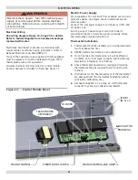
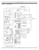
Страница 23: ...23 WIRING DIAGRAMS Figure 12 Control Module Damper is not an option...

Страница 24: ...s Repeat until you have covered every radiation unit in system End at highest unit in system If units have automatic vents manual venting is unnecessary but it will speed up proper filling of system I...

Страница 25: ...ob WARNING If you do not follow these instructions exactly a fire or explosion may result causing property damage personal injury or loss of life This appliance is equipped with an ignition device whi...

Страница 26: ...quire primary air adjustment and are not equipped with primary air shutters Main burner flames form sharp blue inner cones in softer blue outer mantel with no yellow Puffs of air from blow ing on flam...

Страница 27: ...supply to burners 3 Turn your thermostat up to call for heat and let your boiler run until temperature of water reaches limit setting Gas valve shuts off and circulator keeps running until thermostat...

Страница 28: ...ater left in to freeze will crack pipes and or boiler Cleaning Your Boiler And Burners Flue passages between sections should be examined yearly and cleaned if necessary To clean Remove burners pilot a...

Страница 29: ...trical contact Check all control terminals and wire joints Chimney flue is blocked Pressure switch will not close and pilot spark will not operate to start pilot Have your service technician check and...

Страница 30: ...o expand as temperature changes Diaphragm type tank can be mounted on air purger fitting or at any convenient place in supply or return line AIR ELIMINATING FITTING AIR PURGER Air purger is used to re...

Страница 31: ...ed Factory Pressure Switch Set point 0 4 wc for 2 5 section boilers 0 5 w c for 6 7 section boilers Rollout Switch FLAME ROLLOUT SAFETY SHUTOFF Rollout switch is temperature sensitive fuse link device...

Страница 32: ...TT using wire nuts Ensure remaining Molex plug connectors have not worked loose during transit Check sensing bulb is fully inserted in well and is not loose A 3 Adjusting Settings To discourage unauth...

Страница 33: ...ion was not detected and delay is called before retry Recycle delay Flame signal was lost and delay is called before retry 11 Wait for pressure switch to open failed to close Inducer is still off Pres...

Страница 34: ...out models must be reset through key buttons and display On retry models wait for retry or reset at thermostat Check for correct installation and wiring before replacing any component Control module c...

Страница 35: ...ut Soft lockout is reset after one hour if alarm reason disappears 63 Soft lockout maximum number of recycles exceeded Soft lockout 64 Soft Lockout electronics failure On board self diagnostics detect...

Страница 36: ...ged wire Check for cracked ceramic insulator which can cause short to ground and replace igniter sensor if necessary At gas valve disconnect main valve wire from MV terminal Turn on power and set ther...

Страница 37: ...Date Service Performed Company Name Tech Initials Company Address Phone...

Страница 38: ...NOTES...

Страница 39: ...Date Service Performed Company Name Tech Initials Company Address Phone...

Страница 40: ...DUNKIRK BOILERS 2201 Dwyer Avenue Utica NY 13501 web site www ecrinternational com...

Отзывы: