


27
StARtING YouR BoIleR
1. Set the thermostat to lowest setting.
2. Turn off all electric power to the appliance.
3. This appliance is equipped with an ignition
device which automatically lights the burner.
Do not attempt to light the burner by hand.
4. Remove burner access panel.
5. Depress gas control knob slightly and turn
clockwise
to “OFF” position.
NOTE:
Knob cannot be turned to “OFF” unless
knob is depressed slightly. Do not force.
6.
!
WARNING:
Wait five (5) minutes to allow
any gas in the combustion chamber to vent.
If you then smell gas in the appliance area
or near the floor, do not touch any electrical
switch, do not use the phone. Leave the
building immediately and call your gas
supplier. If your gas supplier cannot be
reached, call the fire department. Failure
to do so may result in a fire or explosion.
If you don’t smell gas, go to next step.
7. Turn gas control knob counterclockwise
to “ON.”
8. Turn on all electric power to the appliance.
9. Set thermostat to desired setting.
10. After visually inspecting the flame, replace the
lower front panel.
11.
!
WARNING:
If the appliance will not
operate after several tries, turn the gas
control knob to “OFF” and call your service
technician or gas supplier.
1. Set the thermostat to lowest setting.
2. Turn off all electric power to the appliance if
servicing is to be performed.
3. Depress gas control knob slightly and turn
clockwise
to “OFF” position. Do not
force.
OPERATING INSTRUCTIONS
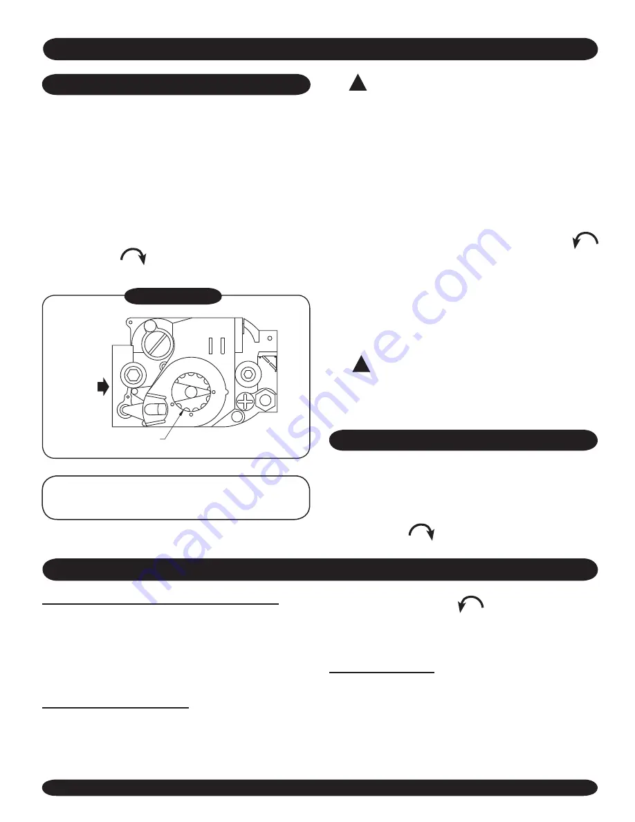
OFF
ON
INLET
GAS CONTROL KNOB
SHOWN IN "ON" POSITION
Figure #13
TO TURN Off APPLIANCE
CheCkING ANd AdjuStING
GAS VALVE SAFETY SHUTDOWN TEST
With main burners firing, disconnect the ignition
cable from the intermittent pilot control box. The gas
valve should shut off the main burners.
TURN OFF
ELECTRIC POWER
to boiler before reconnecting
ignition cable, to prevent electric shock.
ADJUST PILOT BURNER
1. Remove screw cover over pilot adjusting screw.
2. Insert small screwdriver and adjust flame
as needed (
Figure #14
). Turn screw
counterclockwise
to increase flame,
clockwise to decrease (
Figure #15
).
3. Replace screw cover over pilot adjusting screw.
MAIN BURNER(S)
The main burners do not require primary air
adjustment and are not equipped with primary air
shutters. Main burner flames should form sharp
blue inner cones in a softer blue outer mantel, with
no yellow. Puffs of air from blowing on the flame or
stamping on the floor will cause the flames to turn
Содержание XEB-2
Страница 36: ...85 Middle Rd Dunkirk NY 14048 ...


