SolStice
TM
3
explanation of features
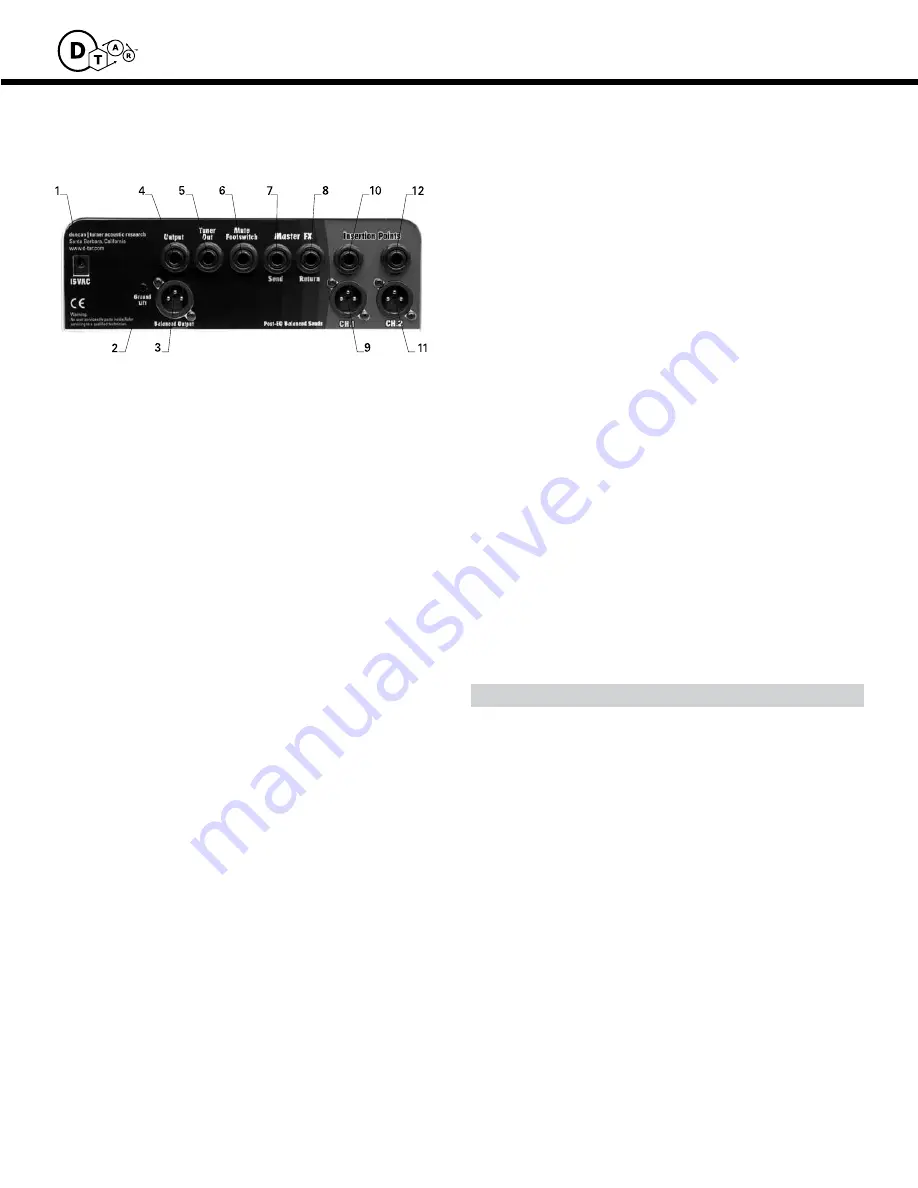
Rear panel
1 Ac power input Jacks
Plug the 15VAC power wall mounted transformer supplied with
the product into this jack.
2 Ground Lift switch
When this button is pushed in, the ground for the Master XLR
Output is lifted. This switch can be useful for breaking ground
loops that can occur during recording sessions. The XLR
ground should typically remain engaged.
3 Balanced Output, Blended signal
This jack provides a balanced, low impedance signal that is
independent of the Master Volume control. It is located near
the end of the signal chain, just before the Master Volume and
is a blended signal of both channels. This output will typically
be used to feed the Solstice’s blended output to a PA or record-
ing system.
4 single ended Output
This jack is located at the end of the signal chain and is
controlled by the Master Volume. It is buffered and provides
very low output impedance. This output will typically be used
to send Solstice’s signal to a power amplifier.
5 Tuner out
This jack provides an auxiliary signal that is located pre-Master
Effects and is unaffected by the Master Volume or the Mute
switch. It is ideal for connection to a tuner, but can be used to
provide an extra output signal for whatever use that comes up.
6 Mute Footswitch Jack
This jack allows remote access to the Mute function. If you
plan to employ remote foot switching, a special stereo foot-
switch is needed in order to have the Mute light turn on and off
properly. A simple schematic is available if you wish to make
your own footswitch.
7, 8 Master effect Loop
These jacks provide send and return locations for an effects
processor. The level is optimized for +4dBu effect processors.
When using –10dBu processors, it may be necessary to reduce
input levels somewhat to avoid overdriving them.
9, 11 channel XLR Balanced Output
This jack provides a balanced, low impedance signal that is
taken post-EQ at the end of each channel’s signal chain but
before any mixing has occurred. It allows the unit to be used
as a stereo mic preamp for recording purposes or provides
individual channel signals to go to a mixing board.
10, 12 channel insertion point / effect Loop
Stereo jacks are provided for each channel to allow flexibility
in the use of effects and in sending and receiving auxiliary
signals. The Send signal is assigned to the Tip and the Return
signal is assigned to the Ring. The tip signal can also be treated
as auxiliary signal outputs and, likewise the ring signal can be
treated as auxiliary signal inputs. These effect loops are series-
type, so inserting or removing a signal will break the internal
signal path. It will be necessary to use a stereo cord and a Y
connector to insert an effects processor (Radio Shack 6 foot Y-
adapter 1/4” stereo to (2) RCA plug cable #42-2547 and 2 each
of RCA plug to 1/4” mono phone plug adapter #274-320). If it is
desired to take an auxiliary signal out, you can simply insert a
standard patch cord. If it is desired to insert an auxiliary signal,
such as a drum machine, it will be necessary to make a cable
with a stereo plug on one end and mono on the other. The
cable must be wired with the tip on the mono end connected
to the ring on the stereo end. The mono end is then connected
to the signal source and the stereo end is plugged into the
Acoustic Mixer channel Insertion jack. As an option, you can
use a Hosa stereo “Y” cord (part #STP-201, 202, 203, or 204)
and just use the mono plug of the “Y” which is connected to
the ring of the stereo plug.
common Problem try the Following Steps
no sound • Make sure power indicator is on
• check mute switch / foot switch
• Make sure your red over-load Led indicator is
flashing to show a signal
• unplug the output to make sure the problem isn’t
further downstream (in the power amp)
distorted sound
• check input level and make sure it’s not overloaded
• Lower effect input level (it may be necessary to raise
the output level of the effect to minimize signal loss)
excessive noise
• input level is set too low
• output level is set too high
excessive hum
• Try unplugging instrument to isolate the source
• check shielding on input devices
• Try ground lift on master balanced (XLr) output
• not enough gain on the mic channel Make sure
20dB pad is not engaged
• excessive amount of eQ boosting
(note: un-buffered high-impedance signals are very suscep
tible to hum) (see excessive noise above)
Troubleshooting Guide:


