2
13) Camera 101
The projector remote control will switch the pro-
jected image between the "computer", "video",
and "s-video". These correspond to the "com-
puter", "DVD/VCR", and the "Camera 101"
images, see Figure 1.
Camera 202, 220
The projector remote control will switch the pro-
jected image between the "computer", "cam-
era", "video" and "s-video" inputs. For
advanced model projectors the "computer" and
"camera" images will appear for the RGB1
(PC1) or RGB2 (PC2) selections, see Figure 2.
If only one computer signal input is present on
the projector, the camera will be used to switch
between the "computer" and the "camera"
image. To accomplish this operation, the
camera remote control "Source" button will
switch between the "PC" and the "camera" out-
puts, see Figure 3.
14) Audio Switching
Most projectors have an internal switch for the
audio that follows the "PC" or "DVD/VCR"
input selection. Such a switch provides the
“Audio Out” from the projector. If an internal
switch is not available a mechanical button
selector switch is located just inside the cart,
see Figure 1.
15) Volume
The volume can be adjusted with the projectors
on screen control or by the speaker unit knobs.
16) The projected image can be keystone corrected
by using the projector controls.
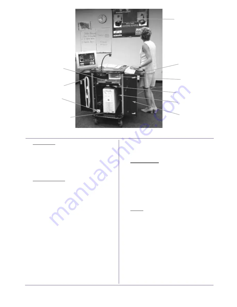
Image on Screen
Folding Shelf on
both Sides
Maximum 14 lbs.
Storage Drawer
Audio Switch for
PC or DVD/VCR
(If required)
Rear of Unit with Tower PC
Maximum tower size
17” H x 17” D
(Tower PC NOT Included)
Open Rear Doors
with Locks
Hooks on Doors for
Cable Storage
DVD/VCR Combo
Power Outlet Strip
. . . continued from front page
Stereo Speakers


