background image

1.6

Lateral setting of needle stab position

Regulation

Both dead centers of the needle lateral motion at the zigzag stitch
sewing should be at the same distance from the throat plate needle
hole edges.

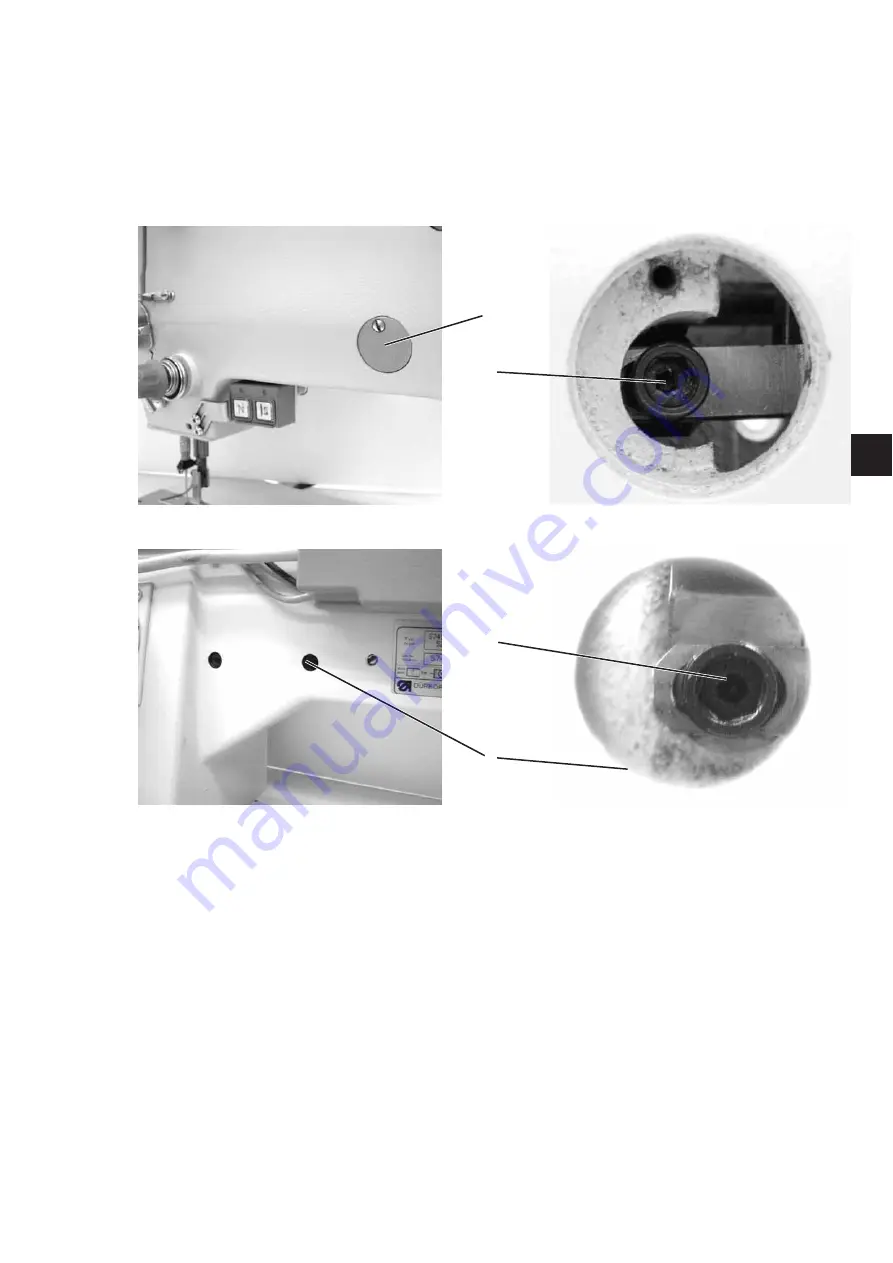
Dismantle the cover (1) and the hole stop (2) from the rear side.

Loosen both screws (3).

Set the maximum zigzag stitch width and adjust the positions of the
needle lateral motion dead centers as per regulation.

Tighten both screws properly (3).

9

G

B

1

3

3

2

Содержание 52Xi

Страница 1: ...ng Postfach 17 03 51 D 33703 Bielefeld Potsdamer Straße 190 D 33719 Bielefeld Telefon 49 0 521 9 25 00 Telefax 49 0 521 9 25 24 35 www duerkopp adler com Ausgabe Edition Aenderungsindex Teile Nr Part No 07 2009 Rev index 00 0 Printed in Czech Republic S735 000805 D GB ...

Страница 2: ...eser Inhalte ist ohne vorheriges schriftliches Einverständnis der Dürkopp Adler AG verboten All rights reserved Property of Dürkopp Adler AG and copyrighted Reproduction or publication of the content in any manner even in extracts without prior written permission of Dürkopp Adler AG is prohibited Copyright Dürkopp Adler AG 2009 ...

Страница 3: ...r all subclasses of the machine and contains also the instructions for setting optional accessories of the machine if this is necessary owing to their complexity Provided the machine supplied does not contain some elements then the respective chapters may be ignored The succession of the setting operations is expressed here by sequencing the paragraphs of this booklet When setting check up if the ...

Страница 4: ...rried out by technicians or persons with appropriate training 7 For service or repair work on pneumatic systems the machine must be disconnected from the compressed air supply system Exceptions to this are only adjustments and function checks made by appropriately trained technicians 8 Work on the electrical equipment must be carried out only by electricians or appropriately trained persons 9 Work...

Страница 5: ...h clearance setting of form stitch gear 12 2 3 Roller bolt position of form stitch steering cam 13 2 4 Setting of needle stab position 14 2 5 Timing of form stitch steering cam to needle motion 14 3 Feeding and presser foot 3 1 Stitch length setting mechanism 15 3 2 Zero stitch length 16 3 3 Feed dog position in throat plate recess and its height 17 3 4 Timing of feed dog motion eccentric in sewin...

Страница 6: ...6 Thread trimmer 6 1 Trimming pressure of trimming knives 30 6 2 Thread trimmer lever 31 6 3 Driver 32 6 4 Thread trimmer cam 33 7 Machine electronic control and drive 34 ...

Страница 7: ...er may arise in any mutual position of the gears Dismantle the machine top cover Loosen the screw 1 and turn the eccentric bolt 2 until the gear fitted on it strikes the gear 3 With regard of the gear runout caused by manufacturing inaccuracy turn the hand wheel by 1 4 revolution and set the clearance again Repeat this 8 times 2 revolutions of the main shaft until the eccentric bolt 2 position wit...

Страница 8: ... onto the casing 3 Place a piece of paper onto the throat plate and turn the hand wheel there and back until the needle point makes 2 holes in the paper Loosen 3 screws 4 and try to set the casing 3 angle position until the needle when being turned stabs there and back in the same hole in the paper Tighten the screws 3 Fix the lever 5 so that the mark 6 is located opposite the zero on the zigzag s...

Страница 9: ...tch length Place a piece of paper onto the throat plate Loosen the screw 1 Try to set the lever 2 in the position corresponding with the required zigzag stitch width Turn the hand wheel there and back until the needle makes 2 holes in the paper Measure their distance Change the lever position 2 until the distance of the holes complies with the regulation Shift the screw 1 to the stop and tighten i...

Страница 10: ...ng direction should be as small as possible Place the needle in the bottom dead center Loosen the arresting screws 1 2 and the regulating screw 3 Adjust the screw 4 so that the regulation is complied with and arrest it with the screw 1 Adjust the regulating screw 3 so that the lost motion play of the needle bar holder in the arrow direction is the smallest achievable one rubbing must not occur Tig...

Страница 11: ...sewing should be at the same distance from the throat plate needle hole edges Dismantle the cover 1 and the hole stop 2 from the rear side Loosen both screws 3 Set the maximum zigzag stitch width and adjust the positions of the needle lateral motion dead centers as per regulation Tighten both screws properly 3 9 G B 1 3 3 2 ...

Страница 12: ...should be approximately in the center of the presser foot or in the middle of the throat plate needle hole center Set the zero width of the zigzag stitch with the lever 1 Loosen the screws 2 Shift the lever 3 until the needle shifts in the lateral direction to the throat plate needle hole center Tighten the screws 2 10 3 2 1 ...

Страница 13: ...central position Loosen the screw 1 and turn the lever 2 in the position in which the needle will perform no lateral motion when turning the lever 3 Locate the stop 4 to the lever 2 and fix it with the screw 1 Loosen the screw 5 and turn the lever 2 to the position in which the needle performs no side motion when moving the lever 3 Locate the stop 6 to the lever 2 and fix it with the screw 5 Adjus...

Страница 14: ...position of the gears Dismantle the top cover Turn the hand wheel 12 times in intervals of approximately 1 3 revolution and ascertain the tooth clearance turning the steering cam 1 manually until the position with the smallest tooth clearance is found Loosen the screws 2 turn the gear in the smallest tooth clearance position shift the cone scroll 3 to the right and set the tooth clearance as small...

Страница 15: ...orm stitch width setting mechanism Release the bolt 1 position by tilting the lever 2 in yourself direction Move the bolt 1 in the arrow direction and watch whether the needle is moving laterally If yes dismantle the steering cam loosen the screw 3 and try to turn the eccentric bolt 4 to a different position and test whether the needle is changing its position Repeat this until the eccentric bolt ...

Страница 16: ...the needle hole center 2 5 Timing of form stitch steering cam to needle motion Regulation When sewing the form stitch the needle should shift in the lateral direction at the time when it is over the sewn material Dismantle the top cover Mount any form stitch cam 1 Loosen 4 screws 2 and turn the scroll 3 to the position where the regulation is complied with Put the scroll 3 on touch with the regula...

Страница 17: ...rform no lost motion Loosen the screws 1 Set the setting knob 2 on the zero stitch length Shift the lever 3 in the arrow direction until its fork is in bilateral contact with the screw spherical end on the knob 2 axis Tighten the screws 1 Check whether the backtacking lever 4 performs any lost motion in this position 15 GB 2 1 3 4 ...

Страница 18: ...gth is set the connecting rod 3 should perform no motion Set the stitch length knob on the zero cipher Tilt the machine and loosen the screw 1 Shift the sleeve 2 until the position is found where the connecting rod 3 stops moving Tighten the screw 1 16 3 2 1 ...

Страница 19: ... with the throat plate Set the zero stitch length Loosen the screws 1 and 2 Shift the whole mechanism laterally so that the feed dog does not touch the throat plate Shift the feed dog so that the spaces 4 and 5 are the same and tighten the screw 1 Loosen the screws 3 turn the eccentric bolt 6 and the lever 7 until the feed dog protrudes from the throat plate by 1 mm in front and at the back Tighte...

Страница 20: ...gth Turn the hand wheel in yourself direction until the needle is in the bottom dead center and then turn until the needle lifts by 1 mm Take care that the needle position remains unaffected and loosen two screws 1 Turn the shaft 2 manually and find its position where the feed dog does not move at the backtacking lever 4 shifting At the same time the longitudinal groove in the roller 3 should be t...

Страница 21: ...e stabs in the material as deep as its eye Tilt the machine and loosen the screws 1 Turn the eccentric bolt 2 in the machine turning direction until the feed dog strikes the sewn material resistance against the eccentric turning will be increased by leap Tighten the screws 1 Test whether the regulation is complied with set the needle eye slightly over the material the material should not move when...

Страница 22: ...should not strike the fixed one Set the maximum stitch length Press the backtacking lever down to the stop and hold it in this position Loosen the screw 1 press the lever 2 down to the stop and put it back by approximately 1 mm Tighten the screw 1 Test whether its movable core does not strike the fixed one when the solenoid is switched on 20 2 1 ...

Страница 23: ...d lever should be 5 5 mm Place the bottom feed dog under the level of the throat plate top surface Place an object of thickness 5 5 mm under the foot Loosen the screw 1 lift the hand lever 2 press the driver 3 down to the lever 2 and tighten the screw 1 21 GB 2 3 1 ...

Страница 24: ... the knee lever is in the initial position Lower the presser foot on the throat plate Loosen the screw 1 and turn the lever 2 so that there is no space A Tighten the screw 1 Try to adjust the ring 3 position and test how big the foot stroke with the knee lever is Repeat this until the prescribed foot lifting is achieved 22 1 2 3 A ...

Страница 25: ...enoid 1 nut Loosen the screw 2 Turn the lever 3 with the roller 4 almost on touch with the side and tighten the screw 2 Remove the solenoid core 5 Loosen the screw 6 and try to turn the screw 7 to any position Insert the core 5 back in the solenoid press it down and find out how big the solenoid stroke is Repeat the procedure until the prescribed value is achieved Lock the screw 7 position with th...

Страница 26: ...k point should be on the needle axis A special fixture is necessary for the setting to make the setting sufficiently accurate Dismantle the throat plate Set the needle bar 1 onto the bottom dead center Fix the sleeve 2 onto the needle bar after having inserted the gauge 3 Remove the gauge 3 Turn the hand wheel until the sleeve 2 shifts to the stop Loosen the hook screws 4 and set its point 5 on th...

Страница 27: ...ottom and the hook point is A 0 2 mm Dismount the throat plate Set the needle stab to the left and the hook point onto the needle axis Loosen the needle bar driver screw 1 and shift the needle bar vertically so that the hook point bottom edge 2 is at the level of the needle eye top edge Tighten the screw 1 Loosen two screws 3 and shift the hook to the distance A Take care that the hook point does ...

Страница 28: ...he distance between the bobbin case driver and the bobbin case groove bottom should be A 0 7 mm Dismantle the throat plate and tilt the machine Loosen the screw 1 Shift the driver 2 to the distance A 0 7 mm Tighten the screw 1 26 2 1 2 A ...

Страница 29: ... and tilt the machine Loosen the screw 1 and shift the casing 2 to obtain the space A 0 8 mm and tighten the screw 1 Turn the hand wheel until the bobbin case lifter 3 is in the maximum lifting position left position Loosen the screw 4 and turn the bobbin case lifter so that the space B 0 4 to 0 8 mm is achieved according to the thread thickness Loosen two screws 5 try to set the timing of the fee...

Страница 30: ... should be pre tensioned by 90Â Set the thread limiter position 1 as shown in the picture and in compliance with the regulation Loosen the screw 5 and turn the whole tensioner 6 so that the spring end 3 is in the same height as the guide top edge 4 Tighten 5 the screw Insert a screwdriver into the groove 7 and turn the shaft thread tensioner bolt anticlockwise until the spring 3 starts turning The...

Страница 31: ...top cover Shift the indented belt 1 with a screwdriver so that two regulating screws are 2 accessible and loosen them Mount the machine arm top cover and switch off the bobbin winder with the lever 3 Insert a hexagonal key through the hole 4 into the regulating screw 2 and shift the indented belt pulley 5 to the left up to the stop Afterwards shift it by 0 5 mm to the right and tighten the screw T...

Страница 32: ... of the trimming knife path only Tilt the machine loosen the screw 1 and remove the bolt 2 Set a high pressure between the trimming knives with the screw 3 so that the resistance against the knife motion is high within the whole motion path Gradually reduce the knife pressure with the screw 3 until compliance with the regulation is achieved Mount the bolt 2 back again 30 3 2 1 ...

Страница 33: ... should be in horizontal position Tilt the machine Loosen the screw 3 and turn the eccentric bolt 4 so that the lever does not rub 6 the plate 5 however it should be positioned as high as possible Tighten the screw 3 Loosen the screw 1 Turn the eccentric bolt 2 so that its groove is almost horizontally positioned Tighten the screw 1 31 GB 6 5 4 3 1 2 ...

Страница 34: ...e driver 1 touches the casing 2 the knife 3 should be on the plate edge 4 Tilt the machine Loosen the screw 5 Shift the knife 3 as per regulation Place the driver 1 on touch with the casing 2 and tighten the screw 5 32 3 4 1 2 5 ...

Страница 35: ...crews should be turned downwards and their axes perpendicularly to the machine base plate Tilt the machine Loosen the screws 1 and 2 set the distance 0 1 mm by shifting the cam 3 and tighten the screws 1 Put the ring 5 on touch with the cam 3 and tighten the screws 2 Loosen the screws 1 Set the needle point to the distance A 1 mm Set the cam 3 with the screws 1 downwards as per regulation and tigh...

Страница 36: ...Detailed instructions for the positioning motor operation are attached to the machine see also www efka net Selected instructions for the drive setting at the machine installation are included in the second part of the Instruction manual 34 ...

Отзывы: