background image

9

ENGLISH

L2000631  Installation guide for DucoBox Focus  (Revision J | 17.07.2019)

07 

Electronical installation

07.A 

Installer / User mode

To add components to the network, remove or replace, the system should be put in ‘Installer mode’� The LED on each component 

indicates the active mode of the component (see table in next section)�

‘Installer mode’ can be activated by pressing the DucoBox Focus ‘INST’ button (see drawing in section "04�A Connections & but-

tons" on page 5�) Once the LED on the master unit starts flashing, it means that ‘Installer mode’ is active� Press ‘INST’ again to 

return to ‘User mode’ (LED fully on or off)� The system reverts automatically to ‘User mode’ after 15 minutes of inactivity�

07.B 

LED indications DucoBox Focus

RED (blinking slowly)

Not in network

RED (blinking rapidly)

Logging in

GREEN (blinking slowly)

In network GREEN

(blinking rapidly)

In network, waiting for associated components

YELLOW (blinking slowly)

Transitional phase (please wait)

YELLOW (on)

Initialising (system configuration in progress)

WHITE or OFF

Normal

BLUE

Component is displayed if changes are being put through via the master�

ORANGE

The system is not working correctly because the DucoBox has not been calibrated� Restart the 

box� Follow the guidelines in ‘10 essential tips’ if the problem recurs continually�

07.C 

Pairing components

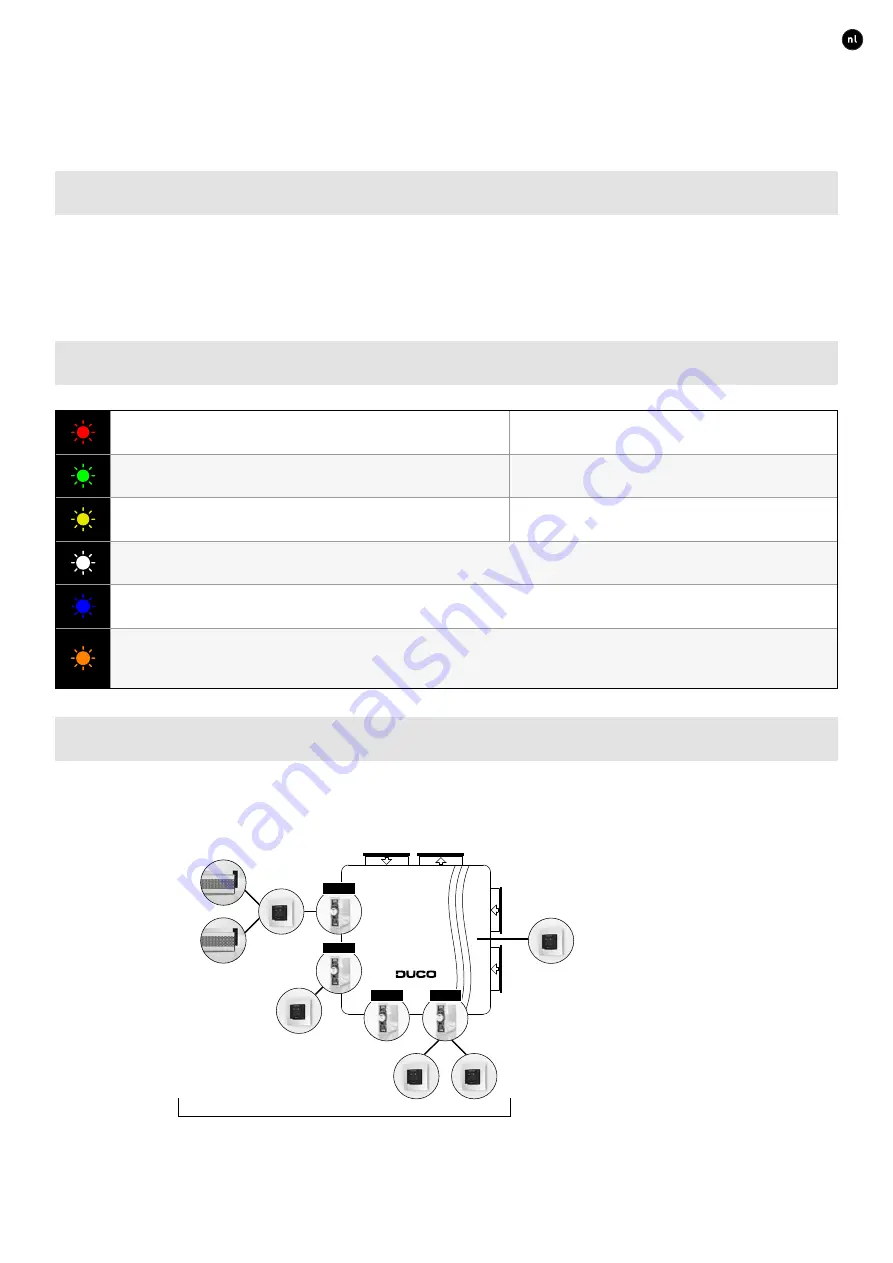
The DucoBox Focus is an extractor fan for a zonal ventilation system� This means that ventilation will only operate in the zones 

where it is needed (e�g� only in the bathroom while showering) for the most energy-efficient operation� Thus, in the example below, 

pressing the button in zone 1 will change the ventilation setting only for this zone� Pressing the button on the master user control 

will control all zones that are set to ‘AUTO’ at that point in time�

Master user control

This controls the 

entire system

ZONE 1

ZONE 2

ZONE 3

ZONE 4

Zonal components

These components only control the zone with which they are paired�

Содержание DucoBox Focus 225

Страница 1: ...H L2000631 Installation guide for DucoBox Focus Revision J 17 07 2019 Installation guide ENGLISH DucoBox Focus Product version 17xxxx and above L2000631 Revision J 17 07 2019 Step by step instructions...

Страница 2: ...nstaller User mode 9 07 B LED indications DucoBox Focus 9 07 C Pairing components 9 07 D Removing replacing components 11 07 E Tips 11 08 Air calibration 12 08 A Air calibration procedure for DucoBox...

Страница 3: ...is exposure to mild levels of noise fire resistant louvres custom louvres for high rise buildings to ventilation and solar shading in a single product or electronically controlled louvres with prehea...

Страница 4: ...m of tiewrap Gebruik geen schroeven bij bevestiging Kies een dakdoorvoer met lage weerstand Houd de DucoBox luchtdicht Sluit het deksel goed en plaats een dop op elke niet gebruikte aansluitmond insta...

Страница 5: ...place any obstacles causing RF interference or other devices with an RF connection within a radius of at least 30 cm around the RF component We take these to include items such as washing machines tu...

Страница 6: ...communi cation Any Tronic grilles will be supplied with a 5 x 0 25 mm cable which can be connected via a splicing terminal block DUCO WIRED Power supply 24 VDC Wiring 5 x 0 75 mm 5 x 0 25 mm from Tron...

Страница 7: ...he LEDs on the DucoBox and control valves will flash green rapidly 3 Long press the button once on the control valve to be removed in order to remove it from the network NB any underlying components w...

Страница 8: ...ms to communicate via ModBus and or ethernet ModBus integration enables them to be linked to a building management system Disconnect the DucoBox from the power supply before connec ting the Communicat...

Страница 9: ...g for associated components YELLOW blinking slowly Transitional phase please wait YELLOW on Initialising system configuration in progress WHITE or OFF Normal BLUE Component is displayed if changes are...

Страница 10: ...s 1 Activate Installer mode by tapping INST on the DucoBox The LED will flash green rapidly 2 Pairing components on the DucoBox Use this method for any components that are required to control the enti...

Страница 11: ...using the palm of your hand on a control featuring touch buttons The LED will turn white Replacing a component 1 Activate Installer mode by long pressing 2 diagonal buttons on a paired control The LE...

Страница 12: ...ition regardless of the desired flow rate When using DucoVent Design exhaust vents leave the ou ter ring in place for acoustic effect SITUATION 2 Multiple vents per valve with equal flow rates Set all...

Страница 13: ...takes 30 seconds 1 minute per connected control valve Iteration Rev Date Name Description 23 Nov 17 Status Date Status STEKKER_STOPCO mm dm m kg m mm Handelsstraat 19 8630 VEURNE tel 0032 58 330033 f...

Страница 14: ...e contact your Duco products seller Keep the serial number of your product to hand 10 Warranty All warranty conditions concerning the DucoBox and Duco s ventilation systems can be found on the Duco we...

Страница 15: ...15 ENGLISH L2000631 Installation guide for DucoBox Focus Revision J 17 07 2019...

Страница 16: ...16 ENGLISH L2000631 Installation guide for DucoBox Focus Revision J 17 07 2019 Installed by L2000631 Document last modified on 17 07 2019 revision J...

Отзывы: