background image

6

5.  Electronical installation

a.  Installer/User mode:

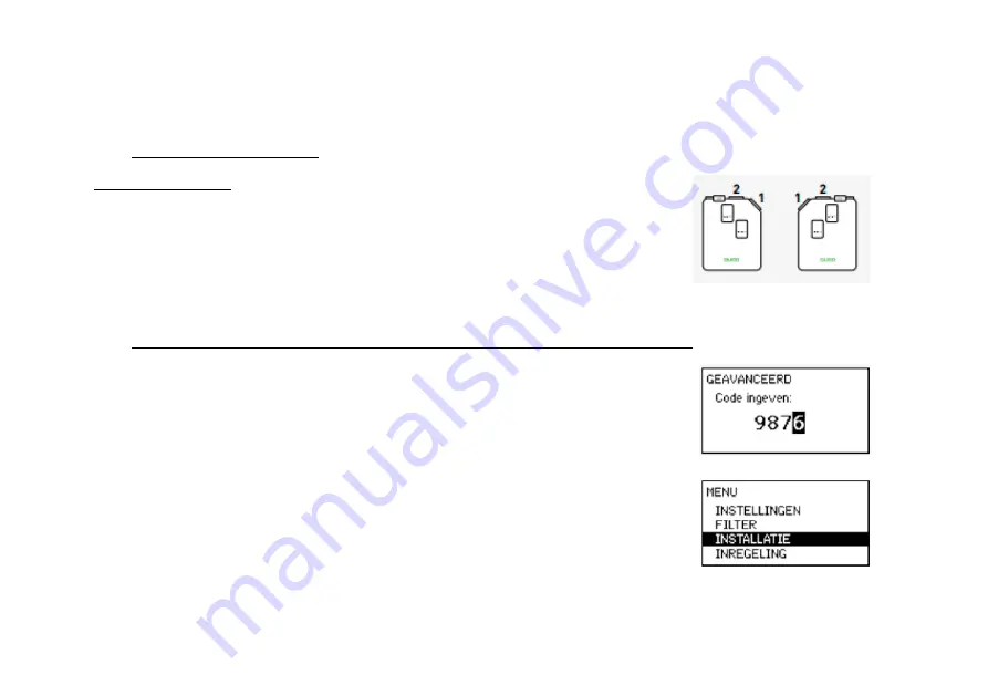
Zone designations
You need to take account of zone designations if you are utilising an integrated 
2-zone system.
Zone 1 is the bevelled side of the DucoBox Energy Premium in each case.

b.  Pairing control components with the DucoBox Energy Premium

1.  Activate advanced mode:
•  Scroll down to ADVANCED and press enter.
•  Enter the installer’s code 9876 and press enter.

2.  Go to the INSTALLATION menu.

Содержание DucoBox Energy Premium

Страница 1: ...DucoBox Energy Premium HANDS ON BE en...

Страница 2: ...sensor only one boxsensor can be connected Pressure sensors Supply Fan Heater 2 Zone Bypass HIGH LOW INST Power 230 VAC Temperature sensors Extract fan DUCO Wired Antenna DUCO Network Tool Switch Cont...

Страница 3: ...king slowly In network GREEN blinking rapidly In network waiting for associated components YELLOW blinking slowly Transitional phase please wait YELLOW on Initialising system configuration in progress...

Страница 4: ...by means of stickers Fresh air Stale air RIGHT HAND configuration EHA SUP1 SUP2 ETA ODA OUTDOORS HOUSE LEFT HAND configuration EHA SUP1 SUP2 ETA ODA OUTDOORS HOUSE Air ducts to HOUSE Air ducts to OUT...

Страница 5: ...steps you can proceed with the following steps in order to complete the installation Pairing control components to the DucoBox Energy Premium 5 a DucoBox Energy Premium air side calibration If there a...

Страница 6: ...ou are utilising an integrated 2 zone system Zone 1 is the bevelled side of the DucoBox Energy Premium in each case b Pairing control components with the DucoBox Energy Premium 1 Activate advanced mod...

Страница 7: ...entire system I e DucoBox Energy Premium without a 2 zone system 1Z types all components DucoBox Energy with a 2 zone system 2Z types components in wet rooms only bathroom toilet kitchen laundry etc 4...

Страница 8: ...g enter 6 For 2 zone system only Pair the desired control components with zone 2 This could be the night zone bedrooms etc Then confirm by pressing enter All components have now been paired This wizar...

Страница 9: ...this removes all paired control components from the network FACTORY RESET this resets the entire system DucoBox Energy Premium paired components to factory settings The calibration will be lost Use t...

Страница 10: ...pending on the situation in accordance with the table below In order to configure the air supply and exhaust correctly these vents must be set so they match the desired flow rate in line with the tabl...

Страница 11: ...r each zone if asked to do so 3 In the Adjust the supply vents step select the duct with the highest flow rate and resistance and using a pressure compensated air flow meter measure the flow rate at t...

Страница 12: ...vents have been calibrated Otherwise you can confirm by long pressing the AUTO button on the User controller Calibrating exhaust vents 6 Repeat steps 3 to 5 inclusive for all exhaust vents 8 Verificat...

Страница 13: ...span of 30 minutes remove and replace operations are ignored Removing a component 1 Activate Installer mode by long pressing 2 diagonal buttons on a paired control The LED will flash green rapidly 2...

Страница 14: ...nication Print Slide the DVAM onto the 4 buses in the DucoBox and connect the cable to the Communication Print connector on the DucoBox PCB see drawing for correct connection 4 Connect the DUCO Wi Fi...

Страница 15: ...15 WIFI PASSWORD 5 6 7 8 3 4...

Страница 16: ...We inspire at www duco eu L2001033 B 26 08 2021...

Отзывы: