8
Position the hanger angles vertically and the drive rail in a line parallel to the gate axis (if there was no need to
move the front fixing relative to the gate axis, the center of the gate will be the center of the drive rail).
Mark, drill and attach the hanger to the ceiling Fig. 6B and, if necessary, shorten the ends of the angles
that protrude downwards.
Move the trolley with the attached bar and gate hardware, Fig. 6C [2..6] towards the closed gate and
centrally (if the entire drive has not been moved) fix the fitting to the gate leaf using self-selected fixing elements,
Fig. 6C [ 7].
Couple the trolley with the door by pulling the cable „backward". The lever to which the cable is attached
must change its position from vertical to horizontal.
Fig. 4.
Initial assembly of the drive.
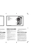
Fig. 5.
Definition of dimensions and recommended values.
A
M10
14mm
B
1
2
D
4xM6
C
E
4xM6
•
THP - the smallest distance between the
top edge of the door and the ceiling
during the opening / closing movement.
This value is minimum 35mm;
•
the distance between the THP and the
running rail should be between 5 and
65mm;
•
the lintel height should be at least 35mm
from the THP.
THP
min. 35mm
5 - 65mm
min. 35mm
5-6
5mm
THP