www.dtresearch.com
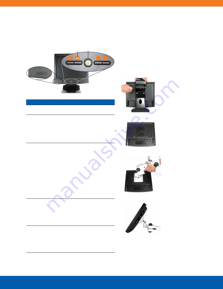
Rear Mounting
The WebDT 550/570 is designed to be secured to VESA-
compliant mounting arms or stands. This is accom-
plished by detaching the standard metal base from the
rear of the display unit. The VESA-compliant mounting
holes at the rear of the device will mate with VESA arms
to meet the requirements of the deployment.
Front Panel Function Buttons
The front panel of the WebDT 550/570 features
control buttons and speaker openings.
Button Description
*
This button is
programmable
via software in the
applicable operating systems.
MENU
Pressing this button will perform one of the following:
4
invoke the MENU for display or device related
features that are adjustable;
4
engage a highlighted MENU or Sub-MENU item;
4
enter or exit Adjustment mode for MENU or
Sub-MENU item
Power
4
May be configured to perform different functions,
depending on the software operating system.
4
Depending on the OS, a brief, firm push will
trigger software-enabled entry into Shutdown or
Standby modes. Push in similar manner to Restart
or to exit Standby mode.
4
Push and hold for over 4 seconds to forcefully
shut down the device.
This method of powering
off should only be used when proper shutdown
through software is not possible.
4
The POWER button is green when the device is
active (i.e.: device is not in Standby or Shutdown
mode, but display may be dark.)
–
Pressing this button outside of the MENU function
will allow the user to ADJUST the Volume. Press
MENU to exit. Pressing this button within the MENU
function will:
4
adjust a selected parameter;
4
navigate among MENU or Sub-MENU items
+
Pressing this button outside of the MENU function
will allow the user to ADJUST the Volume. Press
MENU to exit. Pressing this button within the MENU
function will:
4
adjust a selected parameter;
4
navigate among MENU or Sub-MENU items
*
Menu Power
Built-in
Speakers
+
–
1. Remove the detachable
base by pressing upward
to remove the cover, then
unscrewing the four screws
attaching the base to the
display.
2. The display without the
base.
3. Attach the new VESA-compli-
ant mounting arm or stand to
the display using the same
screws removed in step 1.
4. The display successfully
mounted on a VESA-
compliant mounting arm.
3


