

DT122
ENGLISH
2
3
ENGLISH
THE DT122
Powering ON and OFF
The Power Bu
tt
on is located in the front of the DT122. The Power Bu
tt
on may be con
fi
gured to
func
ti
on di
ff
erently depending on the power op
ti
ons of the opera
ti
ng system. In general, to turn the
DT122 on, push and release the Power Bu
tt
on on the front bezel. The adjacent power LED will be lit
(blue) and the corresponding interface will be displayed on the display monitor.
To turn o
ff
the device, again depending on so
ft
ware opera
ti
ng system, push and release the Power
Bu
tt
on or use a so
ft
ware shutdown interface. In the event of system lockup, the Power Bu
tt
on may
be used to perform a reset on the device. To do that, push and hold the Power Bu
tt
on for at least 4
seconds. The system will shut down and all unsaved work may be lost. Pushing on the Power Bu
tt
on
again will restart the device.
Device Ports
The DT122 features an op
ti
mal set of I/O ports while preserving the compact size of the system. The
HDMI connector, Network (10/100/1000 BaseT Ethernet), and Power ports are supplemented by a
set of four USB 2.0 and two Audio ports. Through its USB ports, the DT122 supports a wide range
of USB-based peripherals. These peripherals are applicable in providing the means for so
ft
ware
installa
ti
on, applica
ti
on storage, data storage, and system so
ft
ware recovery and updates.
Memory and Storage
The DT122 may be available in storage con
fi
gura
ti
ons ranging 8GB to 16GB of
fl
ash memory or
32GB to 64GB SSD. Depending on base so
ft
ware con
fi
gura
ti
on, the user may use the internal
memory of the DT122 for user’s installed so
ft
ware and storage. The user may also supplement
storage space with USB-based peripherals such as
fl
ash disks, disk drives, etc. RAM capacity is up to
2GB.
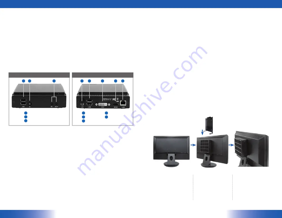
VESA Moun
ti
ng Bracket Installa
ti
on Guide for DT122
The DT122 package includes a VESA-compliant moun
ti
ng bracket (1) which mounts the DT122 (2)
onto a VESA-compa
ti
ble monitor or display.
NOTE:
The VESA Moun
ti
ng Bracket is compa
ti
ble with most displays and monitors that support the VESA standard.
Precau
ti
ons
Always exercise care when opera
ti
ng and handling the DT122.
•
Never disassemble any por
ti
on of the enclosure. It will void any product warranty on the DT122.
•
Do not use any AC/DC adapter other than the one provided with the device or acquired from the
•
manufacturer or its partners.
In the unlikely event that smoke, abnormal noise, or strange odor is present, immediately power
•
down the DT122 and disconnect all power sources.
Please report the problem to your device provider immediately.
•
Rear View
Front View
A
B
C
D
F
E
G
H
DC-in
USB ports (2)
DVI port
HDMI port
Ethernet port
D
F
E
G
H
A
B
C
USB ports (2)
Power bu
tt
on
Audio jacks
Step1:
Locate the exis
ti
ng moun
ti
ng holes on
•
the monitor.
Line the bracket holes up with the holes
•
on the back of the monitor, as shown
to the right.
Place the screws to hold the moun
ti
ng
•
bracket in place and
ti
ghten the screws
(do not over-
ti
ghten).
Step2:
Remove the two M3 screws (3) originally
•
on the DT122 signage appliance.
Place the DT122 (2) on the bracket rail
•
with the interface ports side facing
downwards so that the two moun
ti
ng
holes on the appliance are aligned
with the exis
ti
ng holes on the rail (see
picture).
Step3:
Apply and
ti
ghten the screws into
•
their original loca
ti
ons and make
sure that the bracket and the DT122
are properly secured.


