Operator’s Manual
22
Roller Alignment Instructions
6. Ensure the spring washer stacks are loose. With the rollers apart, push up on the spring washer bolts to verify
there is 0.04-0.08” (1-2mm) of free play in the spring stacks at the top of the bolts. If not, loosen the two
10mm nuts at the bottom of each bolt and adjust using a 5mm Allen wrench. Lock the nuts by turning the
top nut counter-clockwise and the bottom nut clockwise.
7. Slowly lower the top roller until part of it touches the bottom roller. Compare the gap between the rollers
on the left and right side of the machine. If the gap is uneven and the rollers are not parallel, adjust the two
leveling bolts using the process described in Step 5. After making the necessary adjustment, re-check the
gap between the rollers to ensure they are parallel.
8. Repeat Step 6.
9. Test for paper travel at 20-60% pressure by using a roll of Kraft paper that is held to the Infeed Table.
Carefully square it up to the roller. If the paper travels to one side, square up the roll with the roller again
and re-check the travel. If travel is con
fi
rmed in one direction, that is the side that has stronger pressure.
Adjust the spring washer stacks in the right end case to avoid altering the sensor settings in the left end case.
Adjust each stack on the same end so they are as equal as possible. Depending on the paper travel results,
fi
rst loosen the lock nut and then tighten or loosen the adjustment nut. Tightening the adjustment nut will
increase the pressure. Repeat the paper test until travel is less than 0.12” (3mm) for 20’ (6m) of travel.
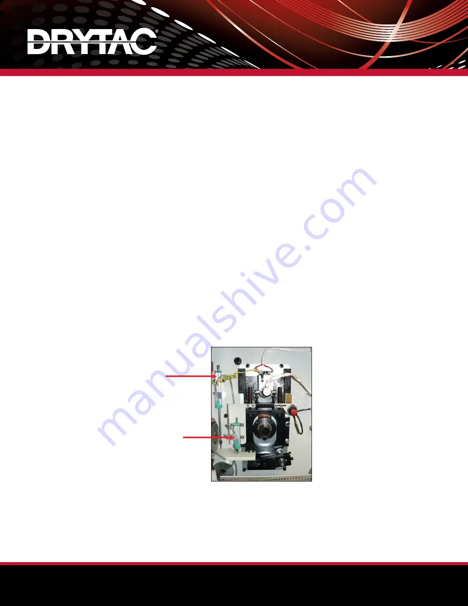
10. Check the height and pressure sensors to ensure proper operation. The height display should read “00” at
the “Sweet Spot” and increase to “01” when the rollers are slightly open. The 0 LED on the pressure display
should be illuminated at all times. When the top roller is lowered to rest on the bottom roller, the 20 LED will
light to indicate 20% pressure has been exerted. If neither condition occurs, the sensor and/or Control Panel
parameters may need adjustment. If the 0 LED is not illuminated when the Nip area is open, the sensor must
be physically adjusted. Proceed to Step 11. If operation is normal, proceed to Step 13.
11. To allow for movement of the pressure sensor, loosen the four bolts that secure the sensor to the support
bracket. Carefully raise the body of the sensor and temporarily secure it with one or two bolts. Check the
display. If only the 0 LED is illuminated, secure the remaining bolts and test functionality. Re-adjust as
needed.
12. To adjust the Control Panel parameters, refer to the Control Panel Parameter Procedure. Do not make
physical adjustments to the sensor without
fi
rst consulting this document.
13. Verify that all bolts are securely tightened before replacing the end case panels and knobs.
Pressure Sensor
Height Sensor


