DOC-0425 Rev D
5
© 2019 DROPLET MEASUREMENT TECHNOLOGIES LLC
Figure 37: SP2-XR Key in the locked (laser off) position .................................................. 49
Figure 38: Cleaning port access to optics ....................................................................... 50
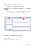
Figure 39: Cleaning the Optics ....................................................................................... 51
Figure 41: SP2-XR Aerosol Flow ..................................................................................... 54
Figure 42: SP2-XR Optical Diagram ................................................................................ 55
Figure 43: SP2-XR Particle trace schematic .................................................................... 57
Figure 44: SP2-XR Mounting Hole Dimensions ............................................................... 63
Страница 1: ...Operator Manual 2400 Trade Centre Avenue Longmont CO 80503 USA DOC 0425 Revision D A L L R I G H T S R E S E R V E D SP2 XR Single Particle Soot Photometer Extended Range...
Страница 2: ...ng 18 1 9 Installation 18 1 10 Setup 18 1 11 Powering the System Down 20 SP2 XR Software 21 1 12 Output Data file types 21 1 13 SP2 XR Quick Start 22 1 14 SP2 XR Main Screen 26 1 15 Histograms Tab 27...
Страница 3: ...Troubleshooting 52 Additional Questions 52 Appendix A Expanded Theory of Operation 53 Appendix B Warranty and Contact Information 56 Appendix C Particle Size Shape determination 57 Appendix D Particl...
Страница 4: ...rograms tab 28 Figure 15 Config Acquisition tab 30 Figure 16 Config Settings tab 31 Figure 17 Config Alarms tab 32 Figure 18 Config Sequences tab 33 Figure 19 Config Custom tab 34 Figure 20 Alarms tab...
Страница 5: ...Key in the locked laser off position 49 Figure 38 Cleaning port access to optics 50 Figure 39 Cleaning the Optics 51 Figure 41 SP2 XR Aerosol Flow 54 Figure 42 SP2 XR Optical Diagram 55 Figure 43 SP2...
Страница 6: ...00 nm mass equivalent diameter assuming a black carbon density of 1 8 g cm3 Maximum Data Acquisition Rate 50 000 particles cm3 10 coincidence at 3 000 Particles cm3 Sample Flow Required 30 120 volumet...
Страница 7: ...on line 1 4 in Swagelok exhaust line fan inlet 1 3 Recommended Maintenance Weekly Routine Maintenance Conduct PSL size check to verify calibration Monthly Maintenance and around field campaigns Conduc...
Страница 8: ...uct names are trademarks or registered trademarks of their respective owners Software License This software is provided by DMT as is and any express or implied warranties including but not limited to...
Страница 9: ...nding on the strength of the laser A diffuse reflection is generally not hazardous but specular reflections can be just as dangerous as direct exposure Protective eyewear is recommended when direct be...
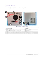
Страница 10: ...in Figure 2 below Figure 2 Front and Rear view of the SP2 XR 1 Power switch 6 HDMI Port 2 Function indicators 7 Monitor Port VGA 3 Inlet flow remove plug prior to power up 8 Ethernet ports 4 Exhaust f...
Страница 11: ...le pulled into SP2 XR The sample is drawn through the sample inlet and then injected into the optical cavity and surrounded by the recirculating sheath flow air system to ensure that the particles are...
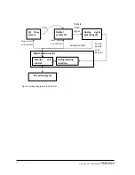
Страница 12: ...am of the SP2 XR Particle photo signal Digital electronics 4 PC and Display 5 Monitor and control Histogramming functions Analog signal processing 3 Optical system 1 2 Flow system Flow control and mon...
Страница 13: ...passes through the optical cavity it will flow through several filters and then either be used as make up air for the sheath flow or it will be ejected through the outlet of the SP2 XR depending on t...
Страница 14: ...emitted during incandescence is measured and a quantitative determination of black carbon mass of the particle is made This mass measurement is independent of the particle mixing state and hence the S...
Страница 15: ...a zero count rate in the incandescence channel and 100nm and 1 10 counts minute at a zero count rate in the scattering channel At this particle size the peak scatter rate corresponds to 100 pW of dete...
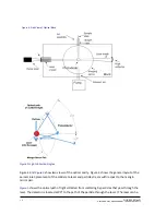
Страница 16: ...e general layout of the aerosol inlet placement of the solid state laser and particle stream with respect to the mangin mirror pair Figure 5 shows the optical path of light collected from scattering b...
Страница 17: ...attered light over solid angles of 900 570 330 1470 excluding the angles subtended by the circular opening of the mangin mirrors 900 14 80 75 20 104 80 For the purpose of calculating scattering cross...
Страница 18: ...supply including regional adapters and an aircraft power integration cable If using in a laboratory setting simply follow section 1 10 Setup to proceed If using in a mobile setting and or on an aircr...
Страница 19: ...y grounded the instrument can cause an electrical shock Use a three conductor cord and a plug appropriate for the location in which the instrument will be used Connect the plug to a properly grounded...
Страница 20: ...will be prevented from being re activated until the laser is turned off Turn off the laser then the pump can be activated CAUTION Make sure the case fans front panel and laser cooling fan underneath h...
Страница 21: ...here will not be saved in the ini file These programs are loaded on the C drive of the SP2 XR and a backup copy is provided on the memory stick shipped with the unit In addition the software to run t...
Страница 22: ...the left and time series plots for recorded parameters on the right Figure 7 Each of the tabs along the top will bring up a new screen allowing for instrument control or display of parameters Figure...
Страница 23: ...the pump and laser are on and running Go back to the Main SP2 XR tab Figure 9 and set parameter A to Sample Flow Controller Read VCCM Other parameters can be chosen by using the up and down arrows to...
Страница 24: ...DOC 0425 Rev D 2019 DROPLET MEASUREMENT TECHNOLOGIES LLC 2 4 Figure 9 Choosing parameters By default the x and y axis of the plots will auto scale as data is collected A...
Страница 25: ...preferred way to close the program as the configurations and files will be saved properly Figure 10 File tab To start recording data choose the Data File dropdown menu and Start Recording see Figure...
Страница 26: ...aved to the file Box B shows the housekeeping time series plots The time series displayed is configurable at points 1 The middle plot can be hidden or shown by using the toggle 2 The Pause Display tog...
Страница 27: ...is labels between counts or concentration in particles per cubic centimeter Cumulative This button is used to accumulate multiple sample periods in the histogram The number of samples accumulated is s...
Страница 28: ...P2 XR software is stored on the C drive Any files saved to the C drive will be deleted upon instrument shut down Data should be stored on the D drive or an external drive Time Range Changes the defaul...
Страница 29: ...rior to making those changes Graph Backgrounds Allows the user to change the default background color of the time series plots The Data File Type The data file types can be selected by clicking the gr...
Страница 30: ...OGIES LLC 3 0 Config Acquisition Tab Figure 15 Config Acquisition tab The Acquisition tab is shown in Figure 15 This tab contains equations for scaling A D counts to housekeeping parameters These valu...
Страница 31: ...togram Settings are the same as described in the Histogram Tab Threshold Tables contain the scattering and incandescence count thresholds for correctly sizing particles These are generated at DMT and...
Страница 32: ...nal That is when an alarm goes from true to false the opposite action is not executed e g Turn Laser Off Alarm will not turn the laser back on when the alarm becomes false Actions will not always use...
Страница 33: ...ach Step Don t Log Allows the user to select whether each step of the sequence will create a log file entry as executed This option creates large log files but adds a lot of detail Create Switch No Sw...
Страница 34: ...have been defined Set Name is a set of parameters that define how the custom display will appear Click on the display set to edit its properties Insert before Insert after can be used to add new Displ...
Страница 35: ...ess the Save Changes button in the upper right hand corner is pressed The software should be restarted with the Restart Program button after saving changes Figure 20 Alarms tab Examples of how to set...
Страница 36: ...would be necessary to define another alarm using the condition and the Set Channel Action Example 3 Name Alarm Alert Channel Error Condition Threshold 0 Hysteresis 0 Action Alert Min Time 0 Set Value...
Страница 37: ...annels can be defined The only parameter for a Timer channel is its name Each Timer starts with a value of 0 when the SP2 XR program starts and counts up in units of seconds A Timer can be set to any...
Страница 38: ...e Sheath and Sample Flow respectively File writing options locations and data file notes input Allows the user to select the type of file maximum size and file location Sequence viewing and toggle on...
Страница 39: ...ow The Utility window has functions and windows for viewing data and logs To open a utility select it from the Utilities dropdown menu Utility Data Reader Figure 22 Utility Data Reader The data reader...
Страница 40: ...019 DROPLET MEASUREMENT TECHNOLOGIES LLC 4 0 Utility Log reader Figure 23 Utility Log Reader The Log Reader allows the user to load a log file to find out more about the status of the SP2XR throughout...
Страница 41: ...nd their current values The left side of the tab contains the current data folder in YYYYMMDD form as well as the data if recording and configuration file names The bottom of the window contains the l...
Страница 42: ...ired For the camera to operate the laser power monitor circuit board must first be removed from the laser cavity The application software can then be started and the beam profile can be viewed 1 21 Ca...
Страница 43: ...REMENT TECHNOLOGIES LLC Figure 26 Front panel connections 2 Tilt the front panel away from the instrument Locate and disconnect the connections for the front panel fan and temperature sensor Figure 26...
Страница 44: ...ard removal 4 With a 1 16 hex driver remove one of the screws from the laser power monitor The second screw only needs to be loosened not fully removed Figure 28 Figure 29 Laser power board removed 5...
Страница 45: ...upplied power Place the power monitor inside the instrument such that it is not between the camera and laser viewing area Figure 29 Figure 30 Front panel connections 2 6 Connect the front panel fan an...
Страница 46: ...w the laser beam profile with the instruments provided third party software For further information on the software see the manual that was provided with the instrument Figure 31 vBeam application 1 W...
Страница 47: ...abeled Select a video board there will be a part number and serial number for the camera similar to MCE B013 U SN XX XXXXXX XXX Click on the part number Figure 32 Figure 33 Resolution and bit depth se...
Страница 48: ...art of the window right of center click the play button to start the camera Figure 34 Figure 35 vBeam exposure time 5 The default exposure time is 90 00ms This will need adjusted change to 50 00ms fir...
Страница 49: ...ved from the unit Figure 36 Cabinet Interlock Switch The second safety interlock comes internally in the form of a key Figure 37 shows the key in the locked position laser disabled In this position th...
Страница 50: ...to clean the optics on site In the event that the user desires to clean the optics without sending to DMT carefully perform the following steps 1 Locate the cleaning port for the mirror optic at the f...
Страница 51: ...to OFF and repeat steps 1 2 of the procedure It may take numerous attempts to return the laser to normal power 4 Reinstall cleaning port and replace the lock down screws 5 If laser reference power is...
Страница 52: ...display Laser off or no sample flow Check that the laser has not shut off Check that the sample flow is positive Check the laser interlocks are engaged i e depressed YAG Output Monitor reference volta...
Страница 53: ...C mass of the particle is made This mass measurement is independent of the particle mixing state and hence the SP2 XR is a reliable measure of the black carbon mass concentration Since the SP2 XR dete...
Страница 54: ...a diagram of the laser and the main optical components The laser cavity consists of a gain medium the YAG crystal and the output coupler The particles from the aerosol jet enter the path of the laser...
Страница 55: ...ne of the SP2 XR optical diagram as shown in Figure 42 The aerosol jet is perpendicular to the plane of the SP2 XR optical diagram and sends the particles across the laser beam Figure 42 SP2 XR Optica...
Страница 56: ...r will pay for shipping to DMT while DMT will pay for the return shipping expense Consumable components such as tubing filters pump diaphragms and Nafion dehumidifiers and dehumidifiers are not covere...
Страница 57: ...ction of electronic noise HWHM Time Max Maximum particle width allows rejection of floater particles Interparticle Time Min Sets a minimum time between any two particles typically set at 0 Threshold M...
Страница 58: ...tter Peak Time Time when scattering signal crosses the threshold until peak height in microseconds Scatter HWHM Half width at half maximum for the scattering peak microseconds Scatter Size nm Scatter...
Страница 59: ...An incandescence signal was detected during the particle capture period Flag Scatter Rejected A scattering signal was detected during the particle capture period but was rejected by the firmware Flag...
Страница 60: ...es in scattering bin 1 through bin N Number of bins is dictated by the threshold table Incand Bin 1 M M number of incand bins Number of particles in Incandescence bin 1 through bin M Number of bins is...
Страница 61: ...Monitor uA Internal diode to the pump laser optical power Laser Driver Current Monitor A Current supplied to the pump laser High Voltage V APD High voltage Bias Purge Flow Monitor sccm Purge flow meas...
Страница 62: ...Type Description Data 2 D array of 32 bit integers I32 Data for Scatter and Incandescence traces Reserved Unsigned 16 bit number U16 Reserved Time Stamp Single Precision Real Packet UTC Time Stamp Re...
Страница 63: ...the bottom of the instrument These must first be removed and the 5 locations may be used for custom mounting solutions Two mounting options are available for mounting that will maintain sufficient air...