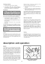
Direct action
With direct positioner action, an increase in the output
signal produces a force on the beam moving the flapper
to cover the nozzle. The increase in nozzle back pressure
increases positioner output pressure to the actuator. The
resultant actuator stem motion is transmitted to the
force-balance spring, extending the spring until the force
exerted on the beam balances the opposing force of the
coil. As these two forces equalize, nozzle back pressure
decreases. The system then is balanced and positioner
output pressure is stabilized at an amount necessary to
maintain the control valve stem in the desired position
corresponding to the input signal value.
Reverse action
With reverse positioner action, an increase in the input
signal produces a decrease in output pressure.
Changing of action
a) Reverse the positions of the coil leads on the
terminal board (see Instruction sheet No ES
50004-000 E, page 3).
b) In case of intrinsically safe circuit, replace the coil by
another one corresponding to the new action
(Instruction sheet No ES 50004-000 E, page 3).
c) In case of flameproof housing device, the
positioner case must not be opened when the
device is energized.
d) Reverse the force balance spring position in regard to
the beam (see corresponding paragraph of page 5).
e) Calibrate after changing of action.
f)
Consult the instruction sheet No ES 50004-000 E.
3
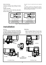
split-range operation
The following instructions apply only when the
positioners are mounted according to the diagrams of
Figure 3.
Therefore, total circuit resistance of positioners installed
for split-range operation must be in accordance with the
total load requirement of the controller. The choice of the
connecting type (in series or parallel) as well as the
positioner characteristics are according to the signal and
to the impedance of the circuits.
Masoneilan supply, in case of need, the data required
for the selection of the equipment or for its modification
in the field.
,,,
,,,
,,,
,,,
,,,
,,,
,,,
yyy
yyy
,
,
,,
yy
,
,
,
,
,
,,
,,
yy
yy
SUPPLY
PRESSURE
OUTPUT
PRESSURE
,
NOZZLE
BACK PRESSURE
SUPPLY
PRESSURE
OUTPUT
TO ACTUATOR
FLAME
ARRESTOR
NOZZLE
FORCE
BALANCE
SPRING
BEAM
FLEXURE
STRIP
COIL
MAGNET
RELAY
O-RING
MOLDED
BRACKET
TERMINAL
BOARD
FORCE BALANCE
SPRING LEVER
CAM FOLLOWER
BEARING
Figure 2– Diagram of Pneumatic Circuit


