


Rev.1.2
Page
4
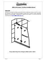
Installation
1. Take out
Stationary glass panel (01)
from the package and find the
Wall Brackets (06).
Attach
Wall Brackets
to the glass panel. Note that the parts of the
Wall Brackets
with the
mounting holes should face inward so that when glass panels are in place, mounting bolts
are only visible from the inside. See fig. 1 for details.
2. Place the
Stationary glass panel
with attached
Wall Brackets
to the designated position
on the threshold or tray, make sure it’s leveled and plumbed and
mark
the position of the
Wall Brackets
on the wall. See Fig. 2 for details.
Be sure that the Stationary glass panel is absolutely vertical.
3. Take the glass panel from the threshold and remove the
Wall Brackets.
4. Using the removed
Brackets
, mark the position of the holes for
Wall Bracket
installation on
the wall. Drill the holes and insert the
Wall
Anchors (07)
into the holes. Attach the
Wall
Brackets
to wall using the
Round head screw ST 4.2×30 (08).
See Fig. 3 for details. (
Note
that all parts of the wall brackets with the mounting holes should face inward in final
installation
).
5. Place the
Stationary glass panel
against the installed
Brackets
and secure it to the wall by
attaching the fastening parts of the
Wall
Brackets
to the mounted parts with the supplied
screws.
Note that the hole in the 72” stationary glass for tray and threshold installation should
be at bottom.
6. Locate the
Support bar (02)
from the package and loosen the glass holding screw on the
gliding channel. Place the
Support bar
with the channel end on the glass top edge and the
bracket end flat on the wall. Adjust the bar to a proper position and level it horizontally. Hold it
firmly and outline the bracket’s position on the wall with a pencil. Take off the
Support bar
and remove the bracket from it. Place the bracket against its position on the wall and mark
the position for the drill hole. Drill the hole, insert the anchor and attach the bracket onto the
wall with
Screw ST 4.2×30 (08)
. Replace the
Support bar
with channel seated on the glass
and the other end underneath the bracket. Attach it to the bracket with the set-screw
provided. Straighten the bar and fasten both set-screws and the glass holding screw to
secure the glass. See fig. 4, 5 for details.
7. Install the
Hinges (03)
onto the stationary glass with the decorative non-screw side facing
outwards. Hook the
Glass door (04)
from inside. See fig. 6 for details.
8. Mount the
Handle (05)
onto the door. Measure the distance between the top edge of the
glass door and upper edge of the top hinge. Cut the piece off the
Side strip (09)
with a knife
in the length according to your measurement. Repeat it to prepare the short strip for the
lower section of the glass door. Then measure the distance between the bottom edge of the
top hinge and the upper edge of the bottom hinge and cut the rest of the strip to size. Open
the door to its full section and push all the strip lengths onto the vertical edge of the glass
door. Push the
Bottom anti-water strip (10)
on the bottom edge of the glass door. See fig. 7
for details.
9. Attach the
Bottom bracket (13)
on the stationary glass and mark a hole in the threshold or
tray through the slotted hole of the
Bracket
. Remove the
Bracket
, insert
Anchor (07)
. Then
reinstall the
Bracket
and screw it onto the threshold or tray with the
Round head screw
ST4.2×25
(11)
and cover it with the
Decorative cover (12)
. See fig. 8 for details.
NOTE: The Bottom bracket (13) is only applicable for 72” shower door installation (to
the threshold or the shower tray). If your unit is being installed to the bathtub, then
you do not need this bracket.
10. Seal with caulk (recommended 100% clear silicone) inside and outside along the bottom of
the stationary glass and between the wall and the wall bracket. See fig. 9 for details.
Содержание AQUA LUX
Страница 5: ...Rev 1 2 Page 5 fig 1 fig 2 fig 3 fig 4...
Страница 6: ...Rev 1 2 Page 6 fig 5 fig 6 fig 7 fig 8...