


7
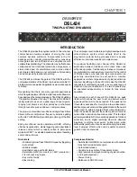
DRAWMER
DSL424 O
PERATOR’S
M
ANUA
L
THE QUICK SETUP PROCEDURE
Quickly Setup the Gate
Select the Key trigger source.
Select Key Listen, and trim down to the desired
frequency for triggering the Gate using the HFand LF
Key filters.
Select the desired amount of reduction using Range.
Normally fully counter clockwise.
Set the Attack, Hold. Decay and Range controls. For
a programme with long legato release, then Release will
also need to be long. Eg. Piano with reverb. For material
with much low frequency content, the Attack will need
to be quite slow, unless a ‘click’ is desired.
Using the Traffic Light LED display, rotate the Threshold
until some gating activity can be seen. As a rule, the
Threshold will need to be about 3dB below the average
input level to both see and hear the dynamic processing.
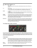
Ratio
Sets the final compression ratio that will be applied once the threshold level is exceeded. The ratio
may be continuously adjusted from 1.2:1 to infinity:1 allowing the possibility of true hard limiting.
Gain
During compression, the signal is attenuated depending on the dynamics of the signal. As a result,
gain may need to be applied in order to produce the desired output level. The GAIN control has a
range of -20dB to +20dB. If the limiter is in operation, only increase GAIN until the limiter operates
on signal peaks. Any further GAIN will just cause excessive limiting, thus reducing the effect of the
compressor.
Bypass
This switch will disable the functioning of the Compressor section and the Peak Limiter. If operating
in Stereo Linked mode, both linked compressor channels will be bypassed simultaneously.
Gain Reduction Meter
An eight segment LED bargraph meter continuously monitors the gain reduction applied by the
compressor/limiter over the range 0 to 30dB.
Output Level Meter
This is a 5-segment LED bargraph level meter that monitors the level of the output signal over the
range -10dB to +10dB.
Peak Limiter
Level
This control sets an absolute limit to the level that the output signal will not be permitted to exceed.
This limiter is very fast acting enabling it to control any peaks without audible distortion. If the output
signal is so high as to cause the limiter to operate for more than 20mS, the system gain is
automatically reduced to bring the signal back within range. The system gain is then returned to
normal over a period of approximately one second.
The compressor Gain control should be used to ensure that the peak limiter operates only rarely
if at all if the limiter is to be used purely for peak protection. Alternatively, the unit may be
deliberately driven into limiting to produce creative effects.
•
•
•
•
•
Quickly Setup the Compressor/Limiter
Select
Hard Knee
if compressing percussive tracks and
Soft Knee
for vocals.
Ensure the
Limiter
control is fully clockwise.
From the programme material, set the
Ratio
. The
ratio
setting depends on how firmly the signal dynamics need
controlling; as a rule, higher ratios provide a higher
degree of control but also tend to be more audibly
apparent in operation when high levels of gain reduction
are required. In general, we suggest less than 2.5:1 for
vocals, less for full mixes, and more for dynamic single
tracks.
Using the VU meter and the Compressor Gain Reduction
(GR) meter, rotate the Threshold until some GR activity
can be seen. As a rule, the Threshold will need to be
about 6dB to 10dB below the average input level to both
see, and hear, much change.
Adjust the Gain to give the desired amount of level on
the VU Meter.
Adjust the Peak Limiter so that the limiter led only lights
on signal extreme peaks.
•
•
•
•
•
•


